Do you have a question about the SICK UE402 and is the answer not in the manual?
Explains the purpose of the operating instructions for the UE402 switching amplifier.
Identifies personnel for whom the operating instructions are intended.
Lists the types of information contained within the operating instructions.
Lists and defines abbreviations used throughout the document.
Explains the meaning of symbols and icons used in the manual.
Defines symbols for sender and receiver in drawings and diagrams.
Explains the meaning of "dangerous state" and its potential causes in machine operation.
Defines the requirements for personnel installing, commissioning, and servicing the UE402.
Describes the intended uses and extensions of the C4000 safety light curtain.
Specifies the correct and intended usage of the UE402 and consequences of misuse.
Provides essential safety procedures and notes for safe operation with the UE402.
Gives guidelines for environmentally responsible disposal of the device.
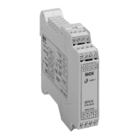
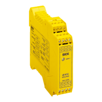
Highlights the key features and extended capabilities of the UE402.
Explains how the UE402 processes signals and interacts with other systems.
Introduces functions selectable via software for the C4000 with UE402.
Explains the bypass function, its activation, and limitations.
Details the PSDI mode, including dual mode and time monitoring.
Defines the PSDI window and its configuration for valid interruptions.
Explains the role of machine cycle contacts in PSDI mode evaluation.
Describes the three possible start sequences for PSDI mode initiation.
Explains the two methods for releasing PSDI control (limited and not limited).
Details the purpose and operation of run-on monitoring.
Describes the eccentric press mode and its protective field muting.
Explains the configurable Teach-in function and its connection.
Details the scope of various configurable functions within the C4000.
Lists configurable functions of the C4000 that cannot be used together.
Explains the states and meaning of the UE402 diagnostic LED.
Illustrates and describes the terminal connections for the UE402.
Explains the connection and use of the operating mode selector switch.
Details the connection and requirements for the key-operated pushbutton for bypass.
Describes the connection of the teach-in key-operated switch to the UE402.
Explains the necessity and types of machine cycle contacts for PSDI mode.
Outlines the steps and requirements for preparing the UE402 configuration.
Provides initial steps and warnings for handling faults and system lock-out.
Instructs users on how to contact SICK Support for unresolved issues.
Explains the meaning of diagnostic LED error displays and remedies.
Details error messages on the C4000's 7-segment display when connected to UE402.
Describes how to perform extended diagnosis using CDS software for troubleshooting.
Presents the technical data and specifications of the UE402 in a tabular format.
Details specifications for input terminals and machine cycle contacts.
Details specifications for input/output terminals.
Lists operational parameters like cable length, temperature, and humidity.
Provides the physical dimensions of the UE402 device.
Lists the components included in the UE402 product delivery.
Lists available accessories for the UE402 with their part numbers.
States the product's conformity with relevant EU directives.
| Number of safe inputs | 2 |
|---|---|
| Number of safe outputs | 2 |
| Supply voltage | 24 V DC |
| Safety Integrity Level | SIL3 |
| Performance Level | PL e |
| Housing material | Plastic |
| Category | Category 4 |
| Switching current | 0.5 A |