Operating Instructions Chapter 3
UE402
8009874/YT67/2016-02-22 © SICK AG • Industrial Safety Systems • Germany • All rights reserved 13
Subject to change without notice
Product description
Device symbol C4000 Host (receiver), context menu Configuration draft, Edit, selection
of the operating mode, file card General, option PSDI window. You must then specify the
beginning and the size of the PSDI window on file card Host or Guest of the system in
question.
Significance of the machine cycle contact for PSDI mode operation
To ensure that the PSDI mode operation is safe and true to the application, C4000 in con-
nection with UE402 evaluates three machine signals:
run-on monitoring (SCC)
Run-on monitoring evaluation is optional.
bottom dead centre (MCC>BDC)
top dead centre (MCC>TDC)
On the basis of the three machine signals, the safety light curtain can identify the
machine’s current cycle phase:
Downward movement of the press. This cycle phase involves danger.
Upward movement of the press. This cycle phase does not involve danger for all
machines.
Stopping the press. This cycle phase does not involve danger provided the “Run-on
monitoring” machine signal is not followed.
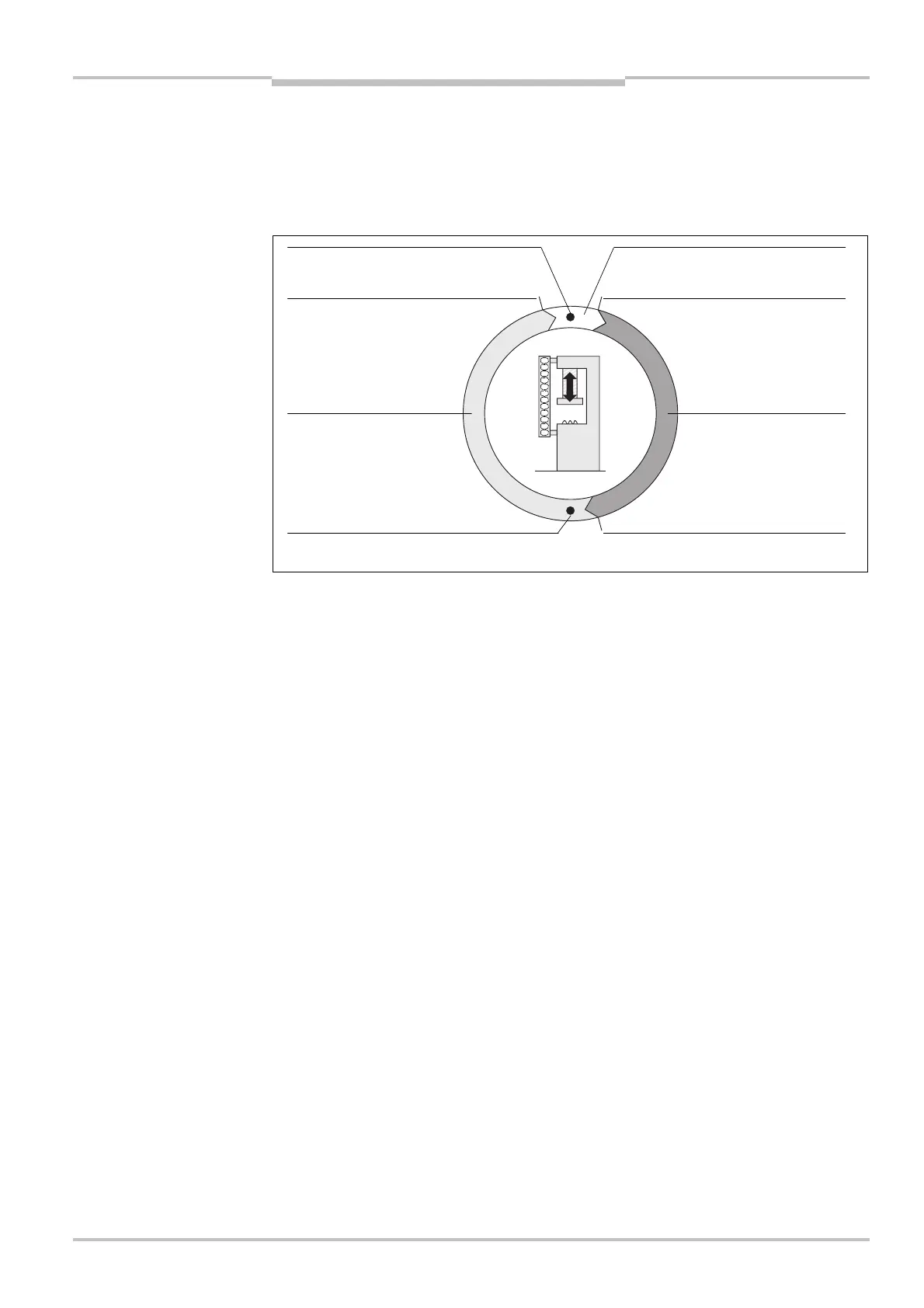
The figure below clarifies the process in time with the aid of an example of the single PSDI
mode:
the machine cycle for PSDI
mode operation for the
example of a press
top dead centre (MCC,TDC)
Machine cycle contact at bottom
press
press
stopping path of the press