Operating instructions Chapter 4
Flexi Classic
8011509/YPP0/2015-10-26 © SICK AG • Industrial Safety Systems • Germany • All rights reserved 65
Subject to change without notice
Special applications and
functions
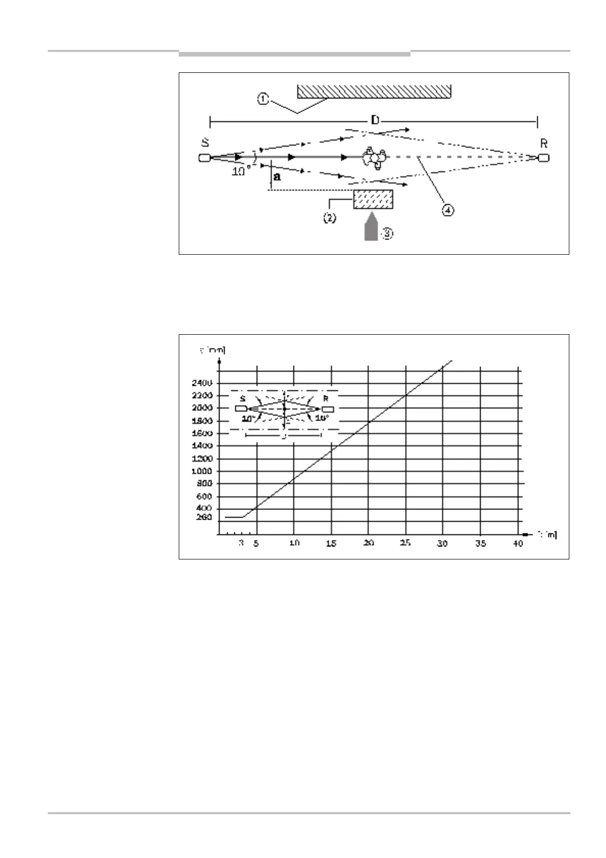
S = Sender R = Receiver
D = Distance sender-receiver a = Minimum distance from reflective surfaces
1 = Limit of the hazardous area 3 = Direction of access to the hazardous area
2 = Reflective surface 4 = Optical axis
The minimum distance (a) to reflective surfaces for single-beam photoelectric safety
switches with a field of view of 10° is calculated as follows:
• If the distance D = 3 m, the minimum distance a = 260 mm.
• If the distance D > 3 m, the minimum distance (a) is calculated using the following
equation:
a (mm) = 88.2 × D × 10³ (m)
Example:
Distance D between the sender and receiver amounts to 28 m.
With the corresponding value entered:
a (mm) = 88.2 × 28 m × 10³ = 2469.6 mm
The minimum distance (a) to the reflective surface has to amount to 2469.6 mm in this
example.
(a) to reflective surfaces,
correct mounting and
(a) as a factor of the distance
D for testable single-beam
photoelectric safety switches
 Loading...
