MLG-2 WebChecker | SICK
Fig. 3 / 그림 3
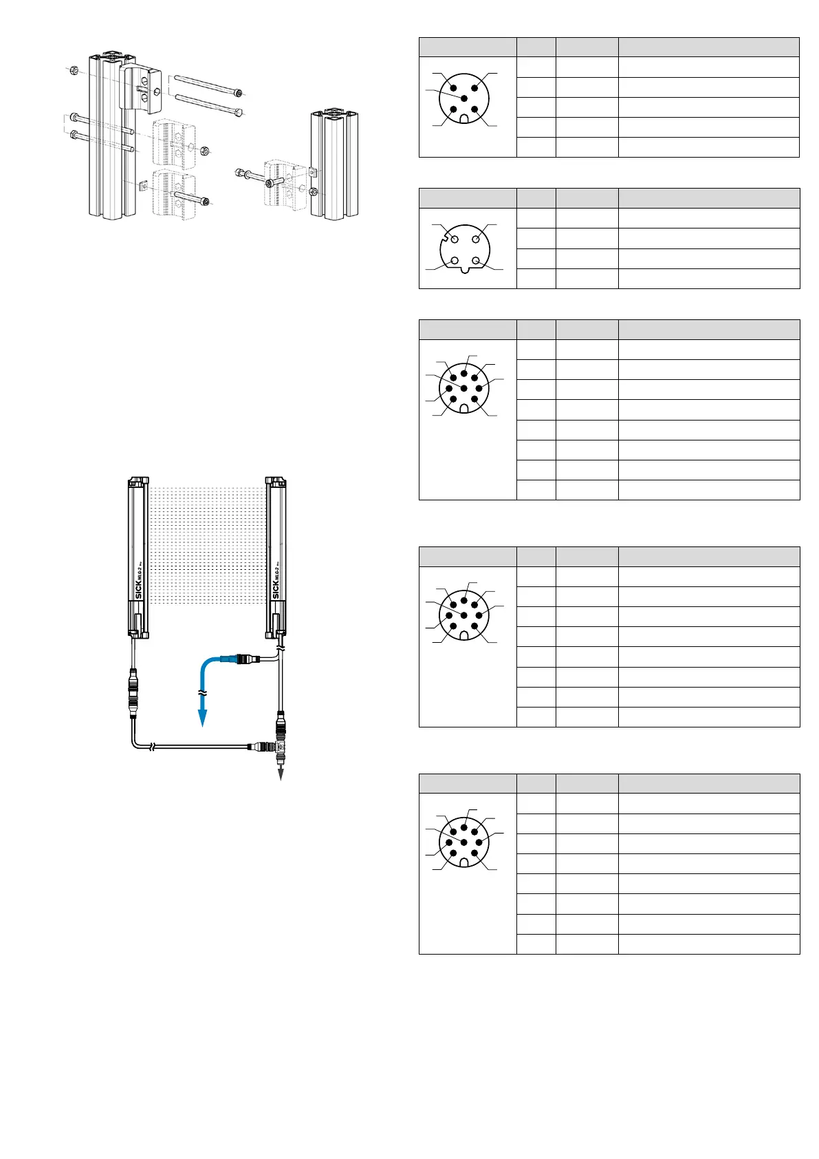
3 Electrical installation
전기 설치
U
B
: 18 ... 30 V DC (without load / 무부하 상태
en
Make the electrical connection in a voltage-free state. Ensure the voltage supply is not
connected.
If the supply voltage is connected, the green LED on the sender and receiver will
be visible.
ko
무전압 상태에서 전기 연결 작업을 하십시오. 전원이 차단되었는지 확인하십
시오.
공급 전압이 걸리는 즉시 송신기와 수신기에서 초록색 LED가 켜집니다.
Example / 예
Fig. 4 / 그림 4
1
2
6
en
1 Connection between Ethernet and receiver
2 Ethernet connecting cable
3 Receiver connection: voltage supply, inputs, outputs and synchronization
4 T-connector (SBO-02F12-SM1: part no.: 6053172)
5 Connecting cable for PLC or IO-Link eld module (DOL-1208-GxxM)
6 Connection cable (DSL-1205-GxxMC)
7 Sender connection: voltage supply, synchronization and test input
ko
1 수신기 Ethernet 연결부
2 Ethernet 연결 케이블
3 수신기 연결부: 전압 공급, 입력, 출력, 동기화
4 T 피스(SBO-02F12-SM1: 품목 번호: 6053172)
5 PLC 또는 IO-Link 필드 모듈 연결 케이블(DOL-1208-GxxM)
6 연결 케이블(DSL-1205-GxxMC)
7 송신기 연결부: 전압 공급, 동기화, 테스트 입력
MLG-2 sender M12, 5-pin, A-coded
Male connector Pin Signal Description
1 L+ 24 V supply voltage
2 Sync_A Synchronization
3 M GND supply voltage
4 Test_In Test input
5 Sync_B Synchronization
MLG-2 receiver M12, 4-pin, D-coded
Female connector Pin Signal Description
1
2
1 L+ Ethernet
2 Sync_A Ethernet
3 M Ethernet
4 Test_In Ethernet
MLG-2 receiver with 4 x Q , M12, 8-pin, A-coded [MLGXXW-XXXXRXXXXX]
Male connector Pin Signal Description
6
4
8
1 L+ 24 V supply voltage
2 Sync_A Synchronization
3 M GND supply voltage
4 Q1/C Switching output 1 with IO-Link
5 Sync_B Synchronization
6 Q2 Switching output or switching input
1
7 Q3 Switching output or switching input
8 Q4 Switching output or switching input
1
1
Congurable
MLG-2 receiver with 2 x QA , M12, 8-pin, A-coded [MLGXXW-XXXXIXXXXX]
Male connector Pin Signal Description
6
4
8
1 L+ 24 V supply voltage
2 Sync_A Synchronization
3 M GND supply voltage
4 Q1/C Switching output 1 with IO-Link
5 Sync_B Synchronization
6 Q2 Switching output or switching input
1
7 QA1 Analog output 1
8 QA2 Analog output 2
1
Congurable
MLG-2 receiver with RS-485 , M12, 8-pin, A-coded [MLGXXW-XXXXBXXXXX]
Male connector Pin Signal Description
6
4
8
1 L+ 24 V supply voltage
2 Sync_A Synchronization
3 M GND supply voltage
4 Q1/C Switching output 1 with IO-Link
5 Sync_B Synchronization
6 Q2 Switching output or switching input
1
7 RS485_A RS-485 interface
8 RS485_B RS-485 interface
1
Congurable
MLG-2 receiver with 3 x Q, 1 x QA M12, 8-pin, A-coded [MLGXXW-XXXXGXXXXX]