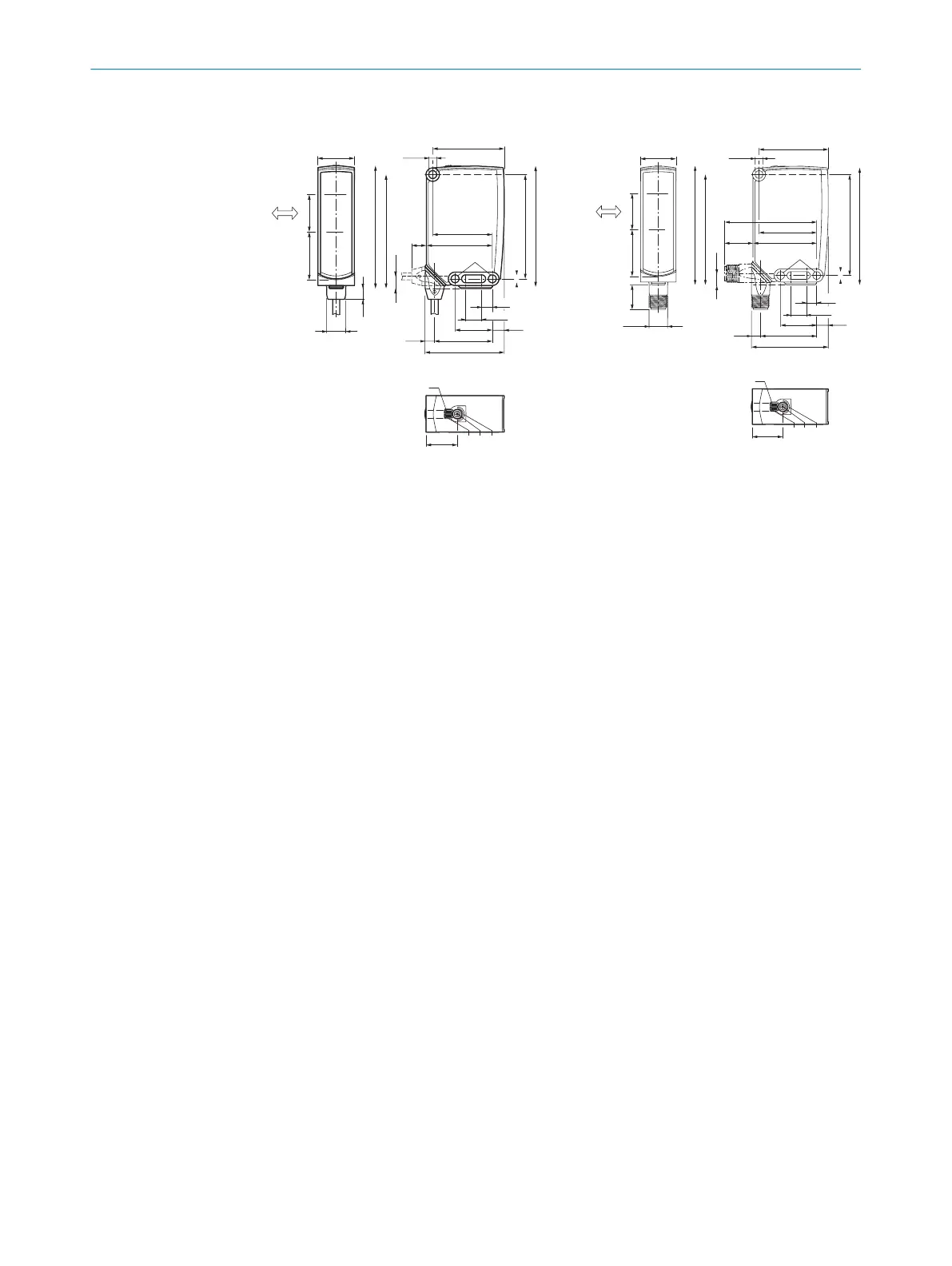
12.1 Dimensional drawings
7,1
8,1
10,8
25
38,8
21
6,4
12,9
48,1
40
10
44,2
Ø 5,2
24,6
82,2
70
Ø 5,2
76,5
8,1
82,5
53,3
7,3
2532,4
1
2
3
5
4
4
89
6
7
Figure 10: Dimensional drawing 1, cable
1
Preferred direction of the target
object
2
Center of optical axis, sender
3
Center of optical axis, receiver
4
Fixing hole, Ø5.2 mm
5
Connection
6
LED indicator green: Supply voltage
active
7
LED indicator yellow: Status of
received light beam
8
Press-turn element: Adjusting the
sensing range
9
BluePilot blue: Sensing range dis‐
play
7,1
8,1
10,8
25
396,3
M12
48,1
40
44,219,7
Ø 5,2
24,6
82,2
70
Ø 5,2
17
7,9
76,5
82,5
2532,4
1
2
3
5
4
4
53,3
63,9
21
89
6
7
Figure 11: Dimensional drawing 2, male
connector
TECHNICAL DATA 12
8020354.14CS | SICK
Subject to change without notice
17