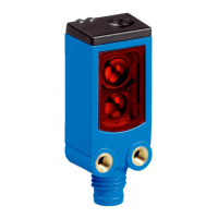
The SICK WTB26 is an opto-electronic photoelectric proximity sensor designed for the optical, non-contact detection of objects, animals, and persons. It operates with background suppression, meaning it can detect an object regardless of the background behind it, provided a minimum distance between the set sensing range and the background is maintained. The sensor is not a safety component in accordance with the EU Machinery Directive.
Function Description:
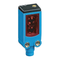
The WTB26 sensor emits a light beam (red light for P-models, infrared for I-models) and detects objects based on the reflection of this light. The sensing range can be adjusted using either a potentiometer or a teach-in button, depending on the specific model. For models with a teach-in button (WTB26 x-xxxxxx2 xAxx and WTB26 x-xxxxxx3 xAxx), the sensing range is adjusted by pressing the button for approximately 1-3 seconds. Fine-tuning can then be done with the potentiometer: clockwise rotation increases the sensing range, while counterclockwise rotation reduces it. For models with only a potentiometer (WTB26 x-xxxxxx1 xAxx), the sensing range is adjusted solely by rotating the potentiometer. The adjustment process typically involves placing the object within the desired sensing range, adjusting the sensor, and then removing the object to ensure the background is suppressed and the switching output changes as expected.
The sensor also features additional functions such as an alarm output and a test input. The alarm output (labeled "Alarm" or "Health" in connection diagrams) provides a pre-failure notification if the sensor is only partially operational. This could be due to contamination, misalignment, or a damaged cable. The LED indicator flashes in this case. The test input ("TI" or "Test") allows the sender to be switched off, enabling a check of the sensor's correct functioning. If an object is detected, activating the test input simulates no object being detected, or the send LED is shut down.
Important Technical Specifications:
The WTB26 series offers various models with different sensing ranges and light types.
- Sensing Range:
- WTB26P-xxxxx1: 30 mm ... 1,600 mm (red light)
- WTB26P-xxxxx4: 30 mm ... 3,000 mm (red light)
- WTB26I-xxxxx1: 30 mm ... 2,000 mm (infrared light)
- WTB26I-xxxxx4: 30 mm ... 3,000 mm (infrared light)
These ranges are based on an object with 90% remission (standard white DIN 5033).
- Light Spot Diameter/Distance:
- P-models: Ø 7 mm (at 700 mm)
- I-models: Ø 14 mm (at 1,000 mm)
- Supply Voltage (UB): DC 10 ... 30 V, with a ripple of ≤ 5 Vss. The device must be supplied by a Class 2 source of supply.
- Current Consumption: ≤ 30 mA (at 16-30 VDC, without load) or < 50 mA (at 10-16 VDC, without load).
- Output Current (Imax): ≤ 100 mA.
- Max. Response Time:
- WTB26P/I-xxxxx1: 500 µs
- WTB26P/I-xxxxx4: 2.5 ms
- Switching Frequency:
- WTB26P/I-xxxxx1: 1000 Hz
- WTB26P/I-xxxxx4: 200 Hz
- Enclosure Rating: IP66, IP67, IP69 (for x4, xH, x5, xl models) and IP65 (for x9, xB models), according to EN 60529 and ISO 20653: 2013-03. UL Environmental Rating: Enclosure type 1.
- Protection Class: III.
- Circuit Protection: Includes UB-connections reverse polarity protected, inputs and output reverse-polarity protected, interference suppression, and outputs overcurrent and short-circuit protected.
- Ambient Operating Temperature: -40 °C ... +60 °C.
Usage Features:
- Operating and Status Indicators: The sensor features LED indicators for various statuses. A blue LED (BluePilot) indicates the sensing range display. A yellow LED indicates the status of the received light beam, and a green LED indicates active supply voltage.
- Alignment: For P-models, alignment involves ensuring the red emitted light beam hits the center of the object. For I-models, the infrared light (not visible) should hit the center of the object, with correct alignment confirmed via the LED indicators. The optical opening (front screen) of the sensor must be completely clear for optimal performance.
- Sensing Range Characteristics: The sensor's performance is influenced by the object's remission. Characteristic lines and diagrams are provided to help determine the minimum distance for background suppression based on the object's remission (e.g., black 6%, gray 18%, white 90%).
- Time Function Setting: The sensor allows for time function settings (M, T1, T2, T3, T4), which can be manually configured via IO-Link for specific applications.
- Electrical Installation: Sensors must be connected in a voltage-free state. Pin assignments for male connectors and wire colors for cables are specified. Voltage should only be supplied after all electrical connections are established.
- Process Data Structure: The sensor supports IO-Link communication (Version 1.1), providing detailed process data including switching outputs (QL1/Boolean, QL2/Boolean, Qint.1/Boolean), time measurement values, counter values, length/speed measurement, and carrier load.
Maintenance Features:
SICK sensors are generally maintenance-free. However, regular checks are recommended to ensure optimal performance and longevity:
- Cleaning: Clean the external lens surfaces regularly to prevent contamination from affecting detection accuracy.
- Connection Checks: Periodically check the screw connections and plug-in connections to ensure they are secure.
- No Modifications: No modifications should be made to the device. Any unauthorized modifications may void warranty claims.
In case of troubleshooting, the manual provides guidance based on LED indicator patterns and fault causes (e.g., IO-Link communication, configuration changes, short-circuits, incorrect sensing range settings).
Disassembly and Disposal:
The sensor must be disposed of according to applicable country-specific regulations. Efforts should be made to recycle constituent materials, especially precious metals, during the disposal process. Batteries, accumulators, and electrical/electronic devices should not be disposed of in general waste but returned to public collection points at the end of their life cycle.