WTB26x-
-xxxxxx1x
-xxxxxx2x
-xxxxxx3x
-xxxxxxx1
-xxxxxxx2
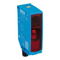
1
BluePilot blue: sensing range display
2
Press-turn element / Potentiometer / Teach-Button: adjusting the sensing range
3
LED indicator yellow: status of received light beam
4
LED indicator green: supply voltage active
5
Press-turn element: time function adjustment
6
Teach pushbutton: adjustment of light/dark switching
4 Mounting
Mount the sensor using a suitable mounting bracket (see the SICK range of acces‐
sories).
Note the sensor’s maximum permissible tightening torque of < 1,3 Nm.
Note the preferred direction of the object relative to the sensorsee figure 10, figure 11.
5 Electrical installation
The sensors must be connected in a voltage-free state. The following information must
be observed, depending on the connection type:
– Male connector connection: Note pin assignment.
– Cable: wire color
Only supply/switch on the voltage once all electrical connections have been estab‐
lished.
Explanations on connection diagram (table 1 - table 4).
Alarm = alarm output
Health = alarm output
MF (pin 2 configuration) = external input, teach-in, switching signal
Q
L1
/C = switching output, IO-Link communication
Test = test input
U
B
: 10 ... 30 V DC
4 MOUNTING
6
8020354.14CS | SICK
Subject to change without notice