10
Midi 201 2904-6 - 2019
Installation
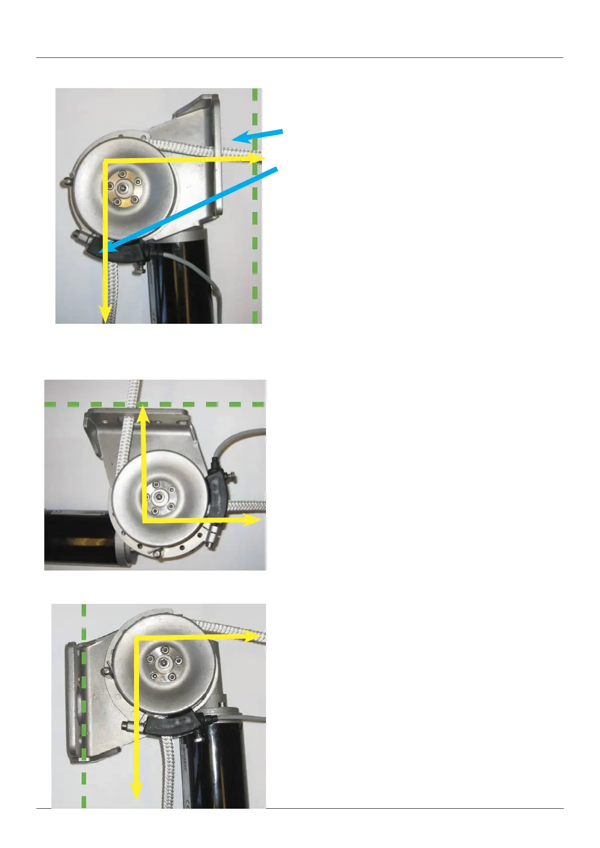
Rope around the line wheel
The mounting bracket for MIDI 201 allows for innitely variable
rotation in relation to the windlass gear/motor.
The bracket for the rope guide/deector can also be rotated inde-
pendently of the gear/motor and mounting bracket. See separate
description.
This description is for installation of the windlass on a vertical cross
bulkhead, on the inside of the stern, for example. The green broken
line indicates the bulkhead that the windlass is fastened to.
It is important that the length of rope that is in contact with the line
wheel is sufcient to ensure good engagement/friction with the
rope. See yellow arrows.
Note! Regardless of how the windlass is fastened to the boat, the
angle between where the rope enters and leaves the line wheel
must be minimum 90 degrees.
This illustration indicates the windlass fastened below deck, etc.
The windlass mounting bracket has been rotated 90degrees
counter-clockwise compared with the illustration above.
The rope comes from above and goes down into the line wheel.
In this case, the rope guide must be adjusted to ensure the rope is
pushed out horizontally from the windlass.
This picture shows the windlass installed on the back side of an
inboard cross bulkhead.
The windlass mounting bracket has been rotated 180degrees coun-
ter-clockwise compared with the illustration on top of this page.
NOTE! The rope is always pulled into the windlass from the right.
This is because of the direction of rotation for the windlass line
wheel.
NOTE! Make sure there is sufcient room to stow the rope below
and next to the windlass.
Remember!
When pulling in the rope for the rst time, you
must keep the rope tight, so the rope run cor-
rectly.