15
Midi 201 2904-6 - 2019
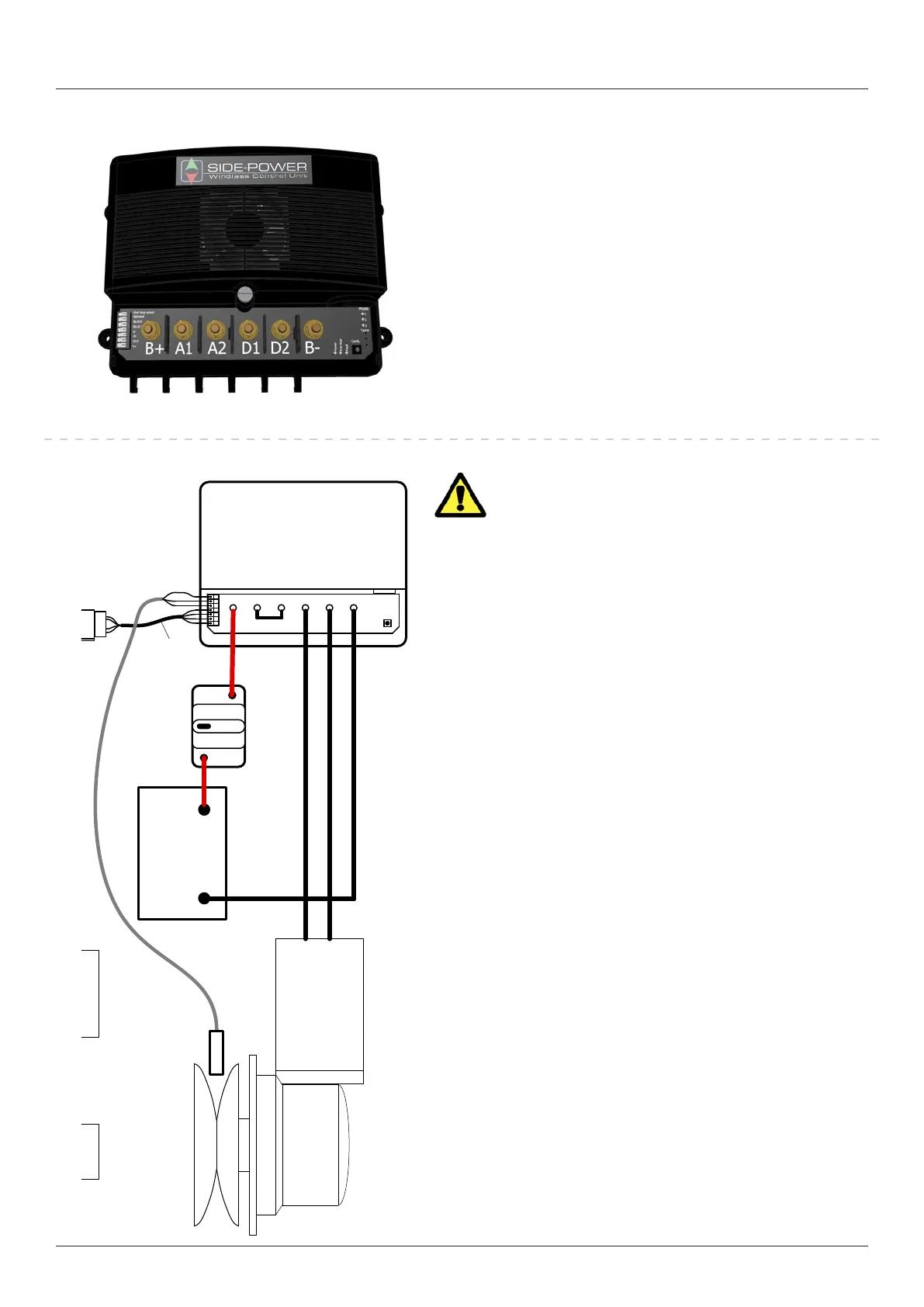
Control unit
Fitting control unit 150800
The unit is not water resiststant and must be placed in a dry area
close to the windlass motor.
Use ring termianls of good quality with the correct size for the
selected battery cables. Bolt hole shuld be 6mm.
Tighten the teminals to maximum 5Nm.
Pay attention to assemble the terminal spacers and washers in the
correct order according to gure 1.
The unit has mounts that ensures space between the unit and it’s
mounting surface. This to avoid condensation to enter the unit. It
also ensures proper ventilation of the enclosure.
The control unit must be mounted with the the cables protruding
downwards.
Connecting the motor and bat-
tery cables on Midi
Motor for windlass type Midi is delivered with cables
tted to the motor.
• Fit included copper link(A1-A2 LINK) between Terminal A1
and A2.
• Connect the red cable from the motor to the Terminal
marked D1/M+.
• Connect the black cable from the motor to the Terminal
marked D2/M-.
• Connect supply cable from battery negative to the Terminal
marked B-.
• Connect supply cable from braker/fuse to the Terminal
marked B+. Connect beaker/fuse to battery main switch.
• See complete wiring diagram on page 6 for reference.
• Tighten all terminals properly, including A1 and A2, with a
maximum torque of 5Nm. Over-tightening may damage the
terminals.
• Leave breaker/fuse disconnected until the installation is
completed.
See control unit manual for configuring and more installation
information.
Electrical installation