11
Midi 201 2904-6 - 2019
A
B
C
Installation
Minimum rope clearance and
height under windlass
In order for the windlass to function normally, there must be a
sufcient volume/height below the windlass for stowing the rope
when the anchor is up.
This table below shows recommended minimum height (A)
below the windlass as well as width (B) and length (C) of the area
used for stowing the rope.
Tau dimensjon. A (cm) B (cm) C (cm)
10 mm x 30 m 35 30 30
12 mm x 30 m 35 30 30
12 mm x 50 m 40 35 35
NOTE! In case of installations where the rope is routed horizontal-
ly out of the windlass when the anchor is up, the relationship be-
tween A, B and C may vary. It is important that there is a sufcient
volume to ensure that the rope is not forced into place below the
windlass and cannot easily be pulled out by the line wheel.
Installation of stop ring for auto
stop
NOTE! Applies to MIDI 201 only
Under the rope guide there is an inductive sensor that signals
auto stop when the anchor has been lifted all the way up. To acti-
vate the detector, two stop rings (included) are tted on the rope.
See procedure below.
The outer diameter of the stop ring must be as close to the outer
diameter of the rope as possible. This is necessary in order for
the inductive detector to be able to detect correctly.
In order to place the stop ring at the correct location on the rope,
lift the anchor until the thimble eye is 25-50 cm below the rope
roller (reel in at slow speed for the last section), and mark the
rope with a marker at the location of the inductive sensor. The
anchor is then reeled in at low speed to the desired nal resting
position. Mark the rope once more by the detector and fasten the
stop rings by the marks.
These stop rings will be exposed to wear by the line wheel,
especially during heavy loads, and must therefore be inspected
regularly. Replace damaged stop rings if needed.
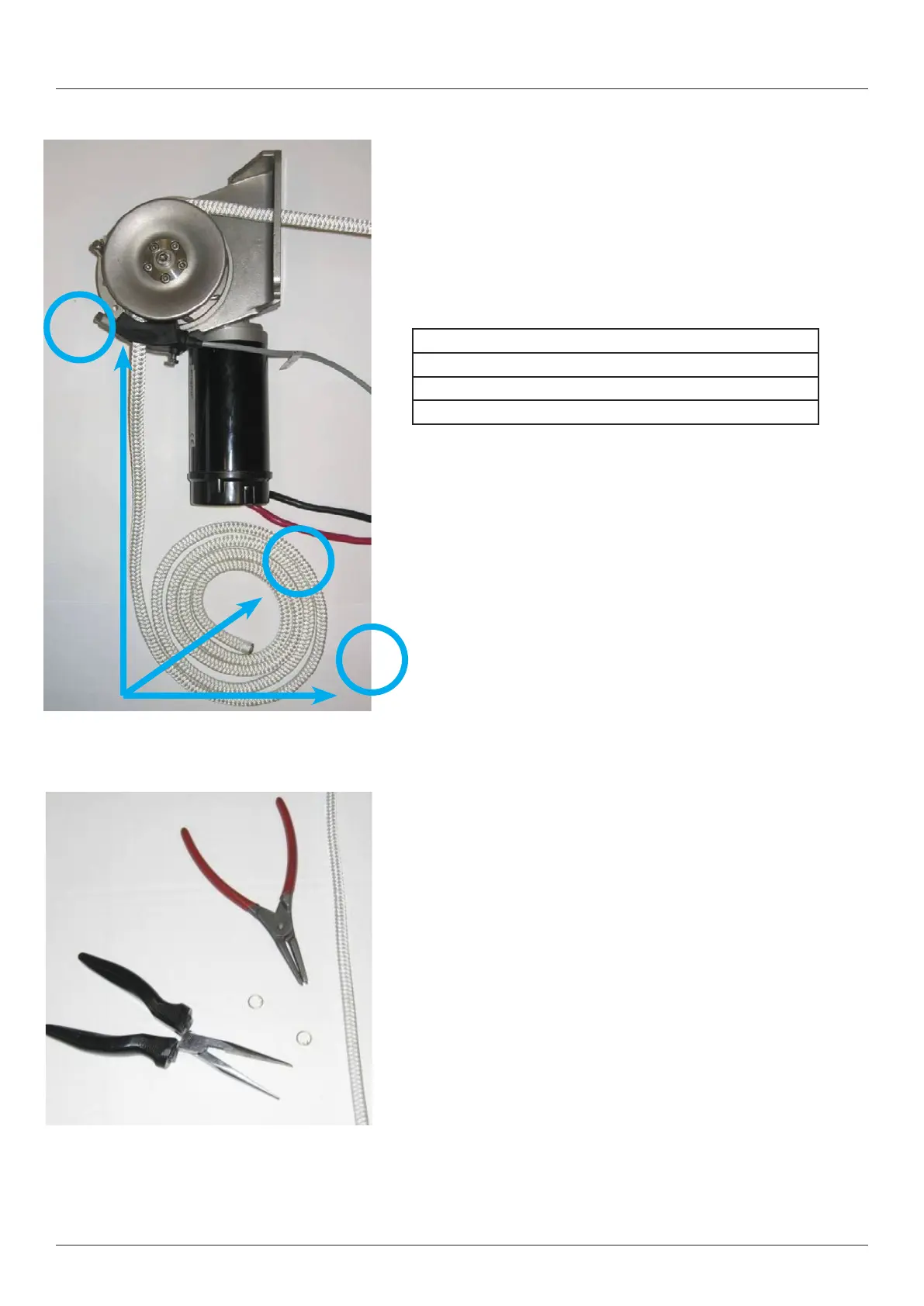
Recommended tools:
• Keeper ring pliers
• Pliers
• Auto stop rings (steel rings enclosed)