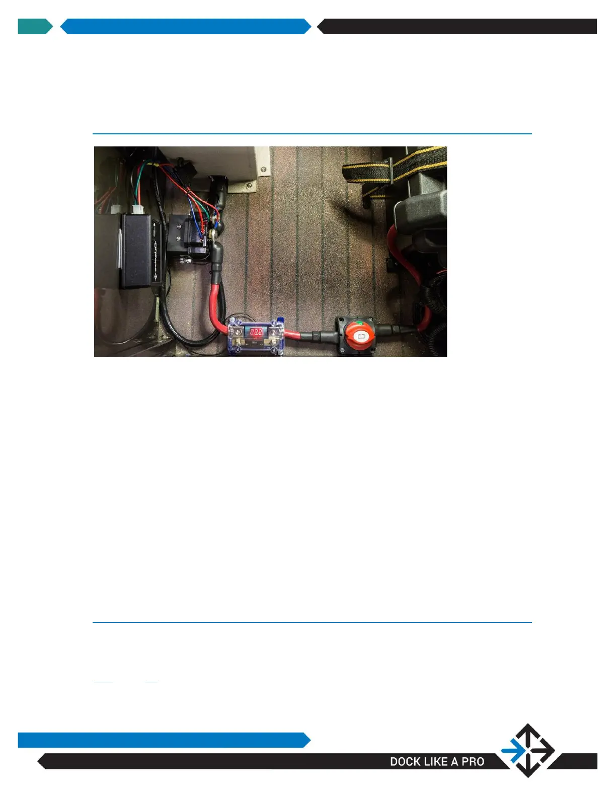
STEP 3: CONNECT THRUSTER BATTERY BANK TO BATTERY
SWITCH, FUSE/VOLTAGE INDICATOR AND MOTOR
CONTROLLER
Refer to relevant schematic starting on page 44 for correct connections.
Fit terminal protectors over each battery lead at the controller end.
Choose a terminal lug to match the cable gauge
1/0 AWG for 230 series connection to motor controller use lug part# T3-1
1/0 AWG for 230 series all other connections use lug part# T3-3
2/0 AWG for 240/340/350 series connection to motor controller use part# T3-2
2/0 AWG for 240/340/350 series all other connections use part# T3-4
Attach positive cable to the “BATTERY POS” post on the motor controller. Slip
battery protector over terminal.
Repeat steps for “BATTERY NEG” cable.
STEP 4: CONNECT BATTERIES
Fit battery protectors and then heat-shrink tube over each battery lead at the battery
end.
See page 43 for instructions.


 To Next Page