Document No. 129-104
Installation Instructions
October 1, 2013
7. Terminate the wires to the termination blocks on the
room unit's base plate. (See
Figure 6.)
8. Feed the extra cable back through the hole.
Sensor Set-up
SEN0589R1
5V
10V
V
I
Jumper
R64 Resistor
(°F/°C Selector)
Voltage/Current
Selector Switch
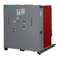
Figure 4. Circuit Board
(Located inside Room Unit Cover.
1. If the device has a switch, determine if voltage or
current output is needed.
• For current, set the switch in the down position
(I).
• For voltage, set the switch in the up position (V).
NOTE: The output setting applies to all outputs
(humidity, temperature, and setpoint).
2. If selecting voltage, set the jumper:
• Use the top and middle pins for 0-5V.
• Use the bottom and middle pins for 0-10V.
NOTE: If the jumper is missing or removed, the
output voltage will default to
0-10V.
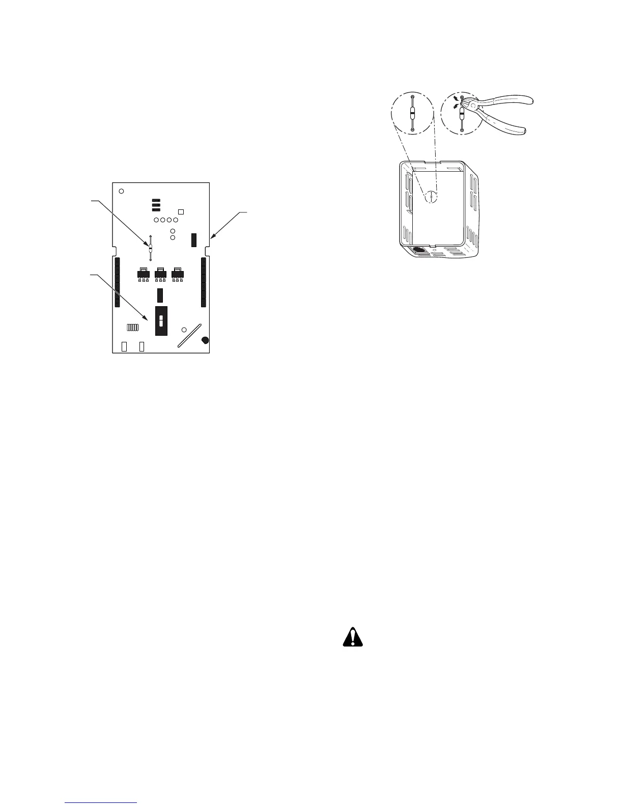
NOTE: The factory default for displayed temperature
units is °F. To change the display to °C, snip the
wire jumper (0 Ohm resistor R64) on the back of
the PCA.
SEN0588R1
°
F
°
C
Figure 5. Changing Display to °C.
3. Snap the room unit cover to the room unit base plate
by first hooking the room unit front to the top latches,
and then rotating the cover downward until it latches.
4. Loosen the safety set screw at the bottom of the
base one or two revolutions to lock the cover to the
base. Be careful not to loosen too far as the screw
can be completely removed from the base.
Electrical Box and Rough-in
Mounting, Typical
1. If a locator is attached to the rough-in device,
remove the locator by removing the two screws and
lightly rocking the locator to pull it free.
2. Untie the twist tie and pull about three inches (75
mm) of the room unit cable through the hole in the
base plate.
3. Mount the room unit base plate on the wall, noting
the UP arrow:
a. Install the two room unit mounting screws
provided, but do not tighten.
b. Level the room unit base plate for appearance
only.
c. Tighten the two mounting screws to the room
unit base plate.
CAUTION:
Over-tightening may cause the room unit
base plate to crack or bend.
4. Continue with Drywall Mounting (No Rough-in),
Typical, Steps 6 through 8, and Sensor Set-up.

 Loading...