EasyManua.ls Logo

Siemens BS-241 User Manual

Siemens BS-241
70 pages
To Next Page IconTo Next Page
Page #1 background imageLoading...
Page #1 background image
Information
Base Station System
Technical Description (TED:BSS)
BS-240/241
A30808-X3247-L14-2-7618

Table of Contents

Question and Answer IconNeed help?

Do you have a question about the Siemens BS-241 and is the answer not in the manual?

Siemens BS-241 Specifications

General IconGeneral
BrandSiemens
ModelBS-241
CategoryAccessories
LanguageEnglish

Summary

Important Safety Notices

Electrical Shock and Death Hazard

Critical safety warning about electrical shock and death, emphasizing following instructions.

1.1 Main Features

System Redundancy and Abis Interface

Core Redundancy

Software support for core redundancy ensures system survival during failures.

AC/DC Power Redundancy

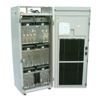
AC/DC converters provide N+1 redundancy for continuous power supply.

Fault Procedures

Automatic Recovery and RF Loopback

Automatic recovery procedures for faulty BTS objects and online RF loopback.

1.2 Technical Data

2 Hardware Architecture

2.1 Board Redundancy

AC/DC Converter Redundancy

Redundancy for AC/DC converters in the service rack.

Core Board Redundancy

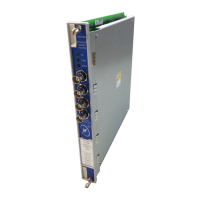
Redundancy for core boards (COBA/COSA) for system availability.

2.2 Power Amplifier Output Level

Carrier Unit Output Power

2.3 Rack Configuration

3.1 Core (COBA and COSA)

3.1.1 Core Basis (COBA2P8)

3.1.2 Core Satellite (COSA6P16)

3.2 Carrier Unit (CU)

PATRX Block Diagram and Functions

SIPRO Unit Functions

3.3 EDGE Carrier Unit

ECU Functionality Overview

Overview of the ECU's role and capabilities for EDGE.

EDGE Unit Features

EDGE Power Amplifier and Tranceiver Unit (EPATRX)

EPATRX Predistortion and Synthesizer Features

Features of EPATRX including predistortion and synthesizer.

Signal Processing Unit (ESIPRO)

EPSU (Power Supply Unit) for ECU

ECU vs. CU Hardware Differences

3.4 GMSK Carrier Units (GCU)

3.5 Duplexer Amplifier Multi Coupler (DUAMCO)

3.6 DI(=2) Amplifier Multi Coupler (DIAMCO)

3.7 Filter Combiner (FICOM)

3.8 Tower Mounted Amplifier (TMA)

3.9 High Power Duplexer Unit (HPDU)

3.12 AC/DC Converter (AC/DC)

3.12.1 DC and Battery Controller (DCBCTRL)

3.13 Overvoltage Protection and Tracer (OVPT)

OVPT Lightning Protection

OVPT provides lightning protection for PCM ports and clock input.

3.17 Backup Battery (BATTERY)

4 Antenna Combiners and Receiving Paths

4.1 Methods of Combining

Methods for combining signals to serve cells with different carrier numbers.

RF Power Combining / Tuning Modes

DIAMCO Module Functionality

High Power Duplexer (HPDU2)

4.1.1 Typical Combiner Losses (TX path)

4.1.2 DUAMCO - DIAMCO GAIN (RX Path)

4.1.3 Parameters of Tower Mounted Amplifier (TMA)

Parameters of 1800 MHz Tower Mounted Amplifier

4.1.4 Examples of possible BTSE configurations

4.2 Receiving Paths

4.2.1 Antenna Diversity Techniques

Techniques for antenna diversity combining.

Switched Combining Diversity

Antenna diversity technique selecting best receiver path based on quality.

Maximum Ratio Combining Diversity

Antenna diversity technique combining all available information from receiver paths.

Receiver Sensitivity

4.3 Transmission Diversity Time Delay

General Transmission Diversity Overview

Overview of transmission diversity time delay and its benefits.

4.3.1 Functionality of Transmission Diversity

Fixed TX Time Shift for Diversity

Method for applying a timing offset to GSM bursts for diversity.

Parallel CU Operation for Diversity

Parallel operation of two CUs for transmission diversity.

4.4 FCC Issues (for US Market only)

Revised FCC Certification for ECU 850

FCC certification adjustments for ECU 850 in the USA.

Revised FCC Certification for ECU 1900

FCC certification adjustments for ECU 1900 in the USA.

5 Power Supply and Battery Backup

5.1 Support of Emergency Operation for 3rd Party BBU System

Support for emergency operation with 3rd party battery backup units.

Related product manuals