Do you have a question about the Siemens BS-240 and is the answer not in the manual?
Provides critical safety instructions for system installation and operation.
Details equipment compliance with standards and operating guidelines.
Explains the purpose and changes for the current document release.
Lists previous versions and their release dates and reasons.
Highlights system capabilities, configurations, and supported services.
Presents key technical specifications like TRX capacity, dimensions, and power.
Ensures system survival through modular architecture and split functions.
Details typical output power levels for various modulation schemes and frequencies.
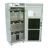
Describes the different rack types and expandable configurations for BS-240/241.
Details the function, configuration, and redundancy of Core boards.
Handles carrier-oriented tasks, including signal processing and RF amplification.
Supports EDGE functionality with modified CU hardware for higher performance.
Combines TX/RX paths for single antenna, includes LNA, splitter, and ASU.
Combines up to 8 frequencies for TX in one rack with low insertion loss.
Provides AC distribution, DC distribution, and power for system operation.
Explains module combinations for performance and cost-effectiveness.
Presents typical insertion losses for various combiner types and bands.
Provides gain parameters for DUAMCO and DIAMCO in AMCO and MUCO modes.
Specifies electrical and system parameters for 900 MHz TMAs.
Discusses antenna diversity techniques and system modules for optimal reception.
Explains methods to achieve optimal receiver sensitivity using DUAMCOs, DIAMCOs, and TMAs.
Describes feature for combining carrier units to increase output power and reduce fading.
Details maximum RF output power values for US market compliance.
Describes emergency configuration triggered by battery discharge alarm.
Provides definitions for technical terms and acronyms used in the document.
| Breaking capacity | 6 kA |
|---|---|
| Mounting type | DIN rail |
| Standards | IEC 60898-1 |
| Rated current | 40 A |
| Number of poles | 1P, 2P, 3P, 4P |