A30808-X3247-L14-2-7618
21
Information
Base Station System
Technical Description (TED:BSS)
BS-240/241
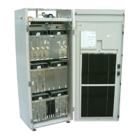
Fig. 2.5 BS-241 Base Rack and 2 Extension Racks
Fig. 2.7 shows the max possible configurations. The Base Rack and the Extension
Racks can be located physically in any position.
The Service Rack (see Fig. 2.6 for possible configuration) satisfies various applications
depending on number of CU units configured and/or number and kind of Network termi-
nation equipment provided and the Battery Backup time required.
All AC/DC frames are housed in the same Service Rack thus there are two basic kinds
of the Service Rack, one being connected to the AC mains (Service1 Rack) and one
being connected to DC only (Service2 Rack).
CU
2
CU
3
CU
6
CU
7
MUCO 0
MUCO 1
CU
0
CU
1
CU
4
CU
5
BS-241
SIEMENS
COBA
0
COSA
0
COBA
1
COSA
1
DC-PANEL
ACT-C
FAN 0
FAN 1
FAN 2
FAN 3
FAN 4*
FAN 5*
ACOM
0
ACOM
1
ACOM
2
ACOM
3
CU
2
CU
3
CU
6
CU
7
MUCO 0
MUCO 1
CU
0
CU
1
CU
4
CU
5
BS-241
SIEMENS
DC-PANEL
ACT-C
FAN 0
FAN 1
FAN 2
FAN 3
FAN 4*
FAN 5*
ACOM
0
ACOM
1
ACOM
2
ACOM
3
CU
2
CU
3
CU
6
CU
7
MUCO 0
MUCO 1
CU
0
CU
1
CU
4
CU
5
BS-241
SIEMENS
DC-PANEL
ACT-C
FAN 0
FAN 1
FAN 2
FAN 3
FAN 4*
FAN 5*
ACOM
0
ACOM
1
ACOM
2
ACOM
3
* not present in case of BTSE with reduced number of fans
 Loading...