Document No. 125-706
Operator Interface Guide
September 19, 2017
Information in this publication is based on current specifications. The company reserves the right to make changes in specifications and models
as design improvements are introduced. Product or company names mentioned herein may be the trademarks of their respective owners.
© 2017 Siemens Industry, Inc.
Siemens Industry, Inc.
Building Technologies Division
1000 Deerfield Parkway
Buffalo Grove, IL 60089-4513
USA
+1-847-215-1000
Your feedback is important to us. If you have
comments about this document, please send them
to SBT_technical.editor.us.sbt@siemens.com
Document No. 125-706
Printed in the USA
Page 4 of 4
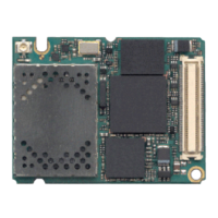
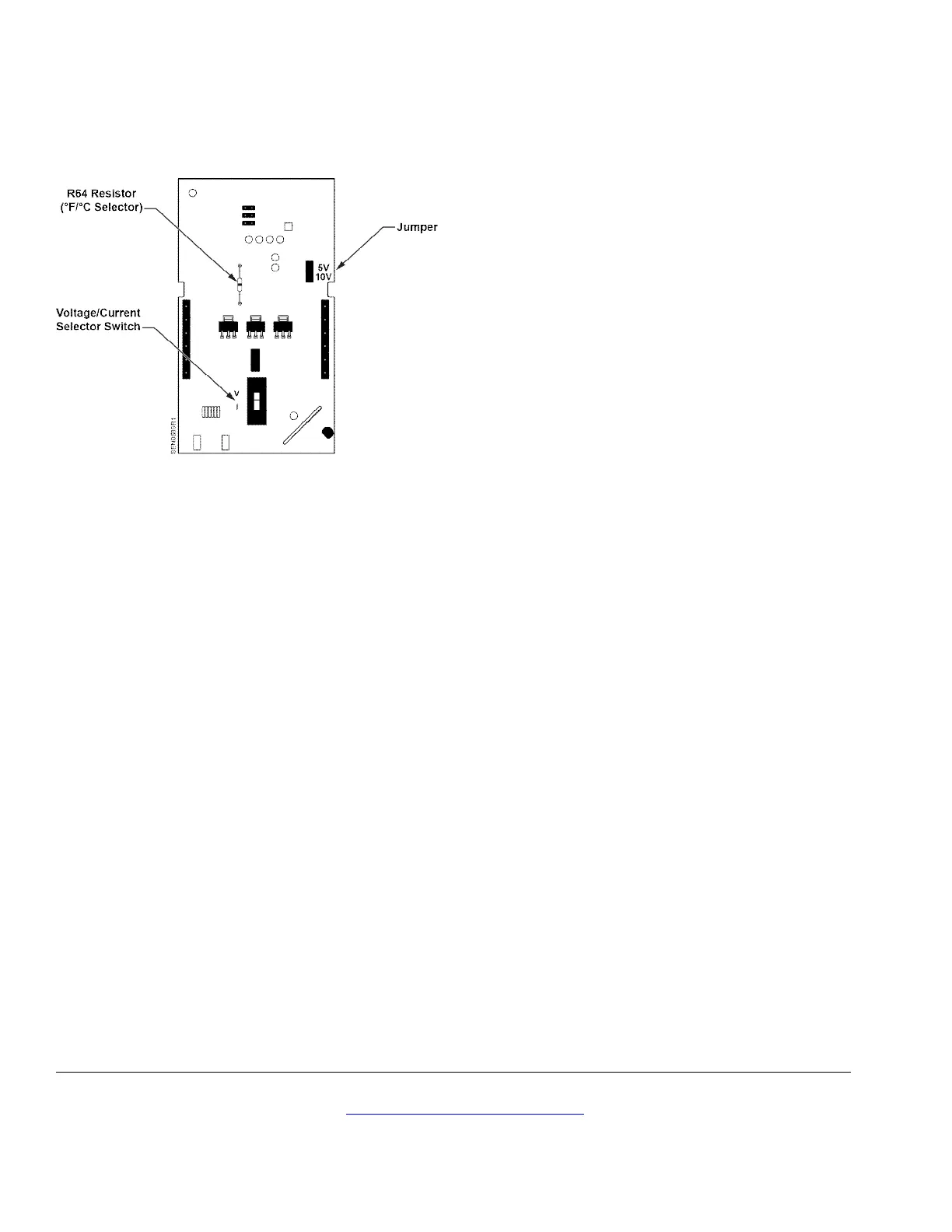
Sensor Set-up
Figure 3. Circuit Board
(Located inside Room Unit Cover.
1. If the device has a switch, determine if voltage or
current output is needed.
• For current, set the switch in the down position
(I).
• For voltage, set the switch in the up position
(V).
2. If selecting voltage, set the jumper as follows:
• Use the top and middle pins for 0 to 5V.
• Use the bottom and middle pins for 0 to 10V.

 Loading...