Connection
20 3ZX1012-0RB22-1AA1
English
4 Connection
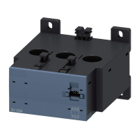
The motor current is measured with the 3RB29.. current
measurement module. The connection of the motor lines is
described in the operating manual 3ZX1012-0RB00-1AA1.
The electronic overload relay is connected with the current
measurement module using a ribbon cable (3RB2987-.) (
Fig. VIII).
Conductor cross-sections and torques in table in
Fig. II.
4.1 Connection diagram
Device circuit diagram (example: Contactor with latching) see
graphic section (
Fig. VIII).
For main current connection for single-phase operation, see
Fig.
VI. No function expansion modules with ground fault detection can
be used here.
4.2 Notes on the protection of device connections
The specifications for short-circuit protection (fuses, circuit
breakers or miniature circuit breakers) are available for the device
connections of the main circuit and of the auxiliary circuit.
In order to enable a holistic assessment of the protection of device
connections, the manufacturer is obliged to provide all relevant
information on short-circuit and overcurrent protection.
For example, if device connections for control supply voltage,
supply voltage or digital inputs and digital outputs are not
connected to self-limiting current or energy sources, you will find
the relevant information in the Equipment Manual or Technical
Data Sheet.
 Loading...