Communication System Manual 3WN1, 3WS1 Circuit-Breakers
108 Copyright Siemens AG 1998. All rights reserved. Version 1.0 (08/98)
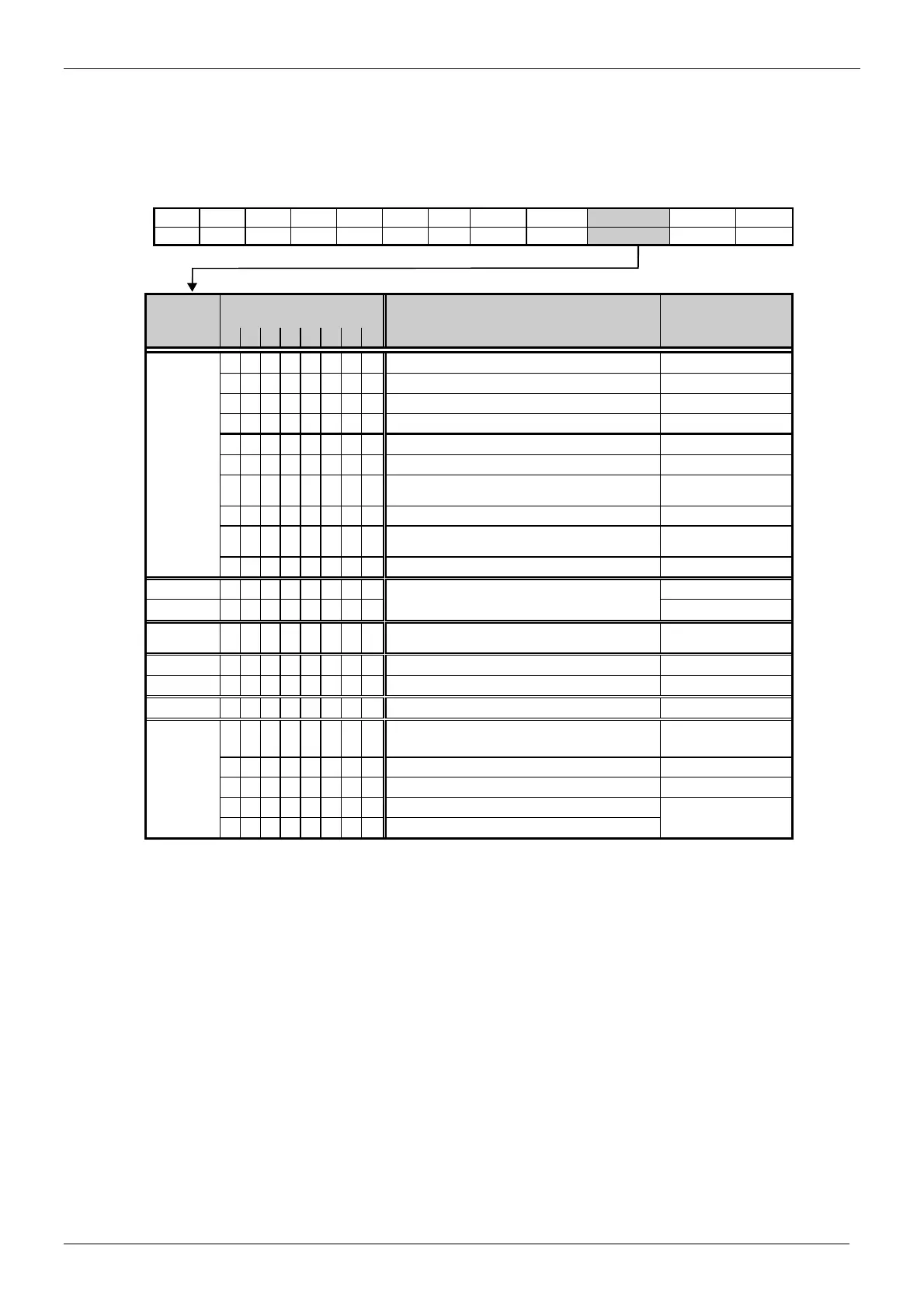
The parameterization message from the master to the interface module is structured as
follows:
Table 17: Parameterization message
SD LE LEr SD DA SA FC DSAP SSAP DU.. FCS ED
68H x x x 8x 8x x 61/3D 62/3E x .. x 16H
Octet Bit no. Description Designation
7 6 5 4 3 2 1 0
1 x x x
Reserved
1
Response monitoring active
WD_On = 0
1
Operate slave in Freeze mode.
Freeze_req
1
Operate slave in Sync mode.
Sync_req
x Unlock
x Lock
0 0
Min. TSDR and slave-specific parameters can be
overwritten.
0 1
DP slave is enabled for other masters.
1 0
DP slave is disabled for other masters. All parameters are
transferred.
1 1
DP slave is enabled for other masters.
2
Time base for watchdog time *
WD_Fact_1
3
(TWS (s) = 10ms*WD_Fact_1 * WD_Fact_2)
WD_Fact_2
4
Time in Tbit which must elapse before the slave
responds. **
min_TSDR
5
High ID number
Vendor_ID_high
6
Low ID number
Vendor_ID_low
7 Group_Ident
8 0 0 0 0 0
Parameterization byte for PROFIBUS
controller SPC3
User_Prm_data
***
0 0 0 0 0 1
This bit disables start bit monitoring in the receiver. Dis_Startbit
0 0 0 0 0 1
This bit disables stop bit monitoring in the receiver. Dis_Stopbit
0 0 0 0 0 0
Time base for watchdog = 10 ms WD_Base
0 0 0 0 0 1
Time base for watchdog = 1 ms
* The time base for the watchdog time is specified as 10 ms in octets 2 and 3. Nothing lower than the digit "2" should ever
be entered in one octet and nothing lower than the digit "1" in the other, in order to ensure that the watchdog time does not
elapse too quickly. A time base of 1 ms is specified in the user parameters of some ASICs due to the 12 Mbaud technology.
** 11 Tbits minimum are specified as standard. This value must be less than the maximum TSDR.
*** The structure of the parameterization message is partly specified as is the case with ASICs LSPM2/SPM2. The SPC3
evaluates the first 7 (without user_prm_data) or the first 8 (with user_prm_data) data bytes. The first seven bytes are defined in
accordance with the standard. The eighth byte is used for SPC3-specific properties and the other bytes are available for the
application.
Response from slave
The slave responds to a parameterization message with "E5H" (short acknowledge). The slave does not
report parameterization errors until later when it receives a diagnostic request from the master.

 Loading...