Communication System Manual 3WN1, 3WS1 Circuit-Breakers
112 Copyright Siemens AG 1998. All rights reserved. Version 1.0 (08/98)
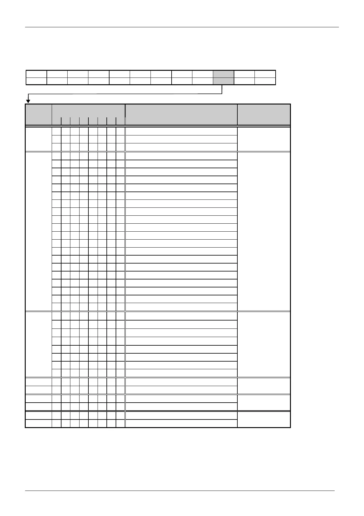
The interface module sends the following data to the master module:
Table 20: Data message
SD LE LEr SD DA SA FC DSAP SSAP DU FCS ED
68H x x x x x x x x x .. x 16H
Octet Bit no. Description
7 6 5 4 3 2 1 0
1 0 0 Maximum phase current in phase L1 1 input byte
0 1 Maximum phase current in phase L2
1 0 Maximum phase current in phase L3
2 0 0 0 0 Rated circuit-breaker current Test 1 input byte
0 0 0 1 Rated circuit-breaker current 315 A
0 0 1 0 Rated circuit-breaker current 400 A
0 0 1 1 Rated circuit-breaker current 500 A
0 1 0 0 Rated circuit-breaker current 630 A
0 1 0 1 Rated circuit-breaker current 800 A
0 1 1 0 Rated circuit-breaker current 1000 A
0 1 1 1 Rated circuit-breaker current 1250 A
1 0 0 0 Rated circuit-breaker current 1600 A
1 0 0 1 Rated circuit-breaker current 2000 A
1 0 1 0 Rated circuit-breaker current 2500 A
1 0 1 1 Rated circuit-breaker current 3150 A
1 1 0 0 Rated circuit-breaker current 4000 A
1 1 0 1 Rated circuit-breaker current 5000 A
1 1 1 0 Rated circuit-breaker current 6000 A
1 1 1 1 Rated circuit-breaker current 6300 A
0 0 Actually displayed phase L1
0 1 Actually displayed phase L2
1 0 Actually displayed phase L3
1 1 Actually displayed phase Lmax
3 1 Button pressed on display 1 input byte
1 "a" release
1 "n/z" release
1 "g" release
1 Phase imbalance
1 Watchdog (microprocessor fault)
1 Overload
1 Temperature alarm
4 Phase 1 current: high-order byte 1 input word
5 low-order byte
6 Phase 2 current: high-order byte 1 input word
7 low-order byte
8 Phase 3 current: high-order byte 1 input word
9 low-order byte

 Loading...