Communication System Manual 3VF Circuit-Breakers
Copyright Siemens AG 1998. All rights reserved. Version1.0 (05/98)
14
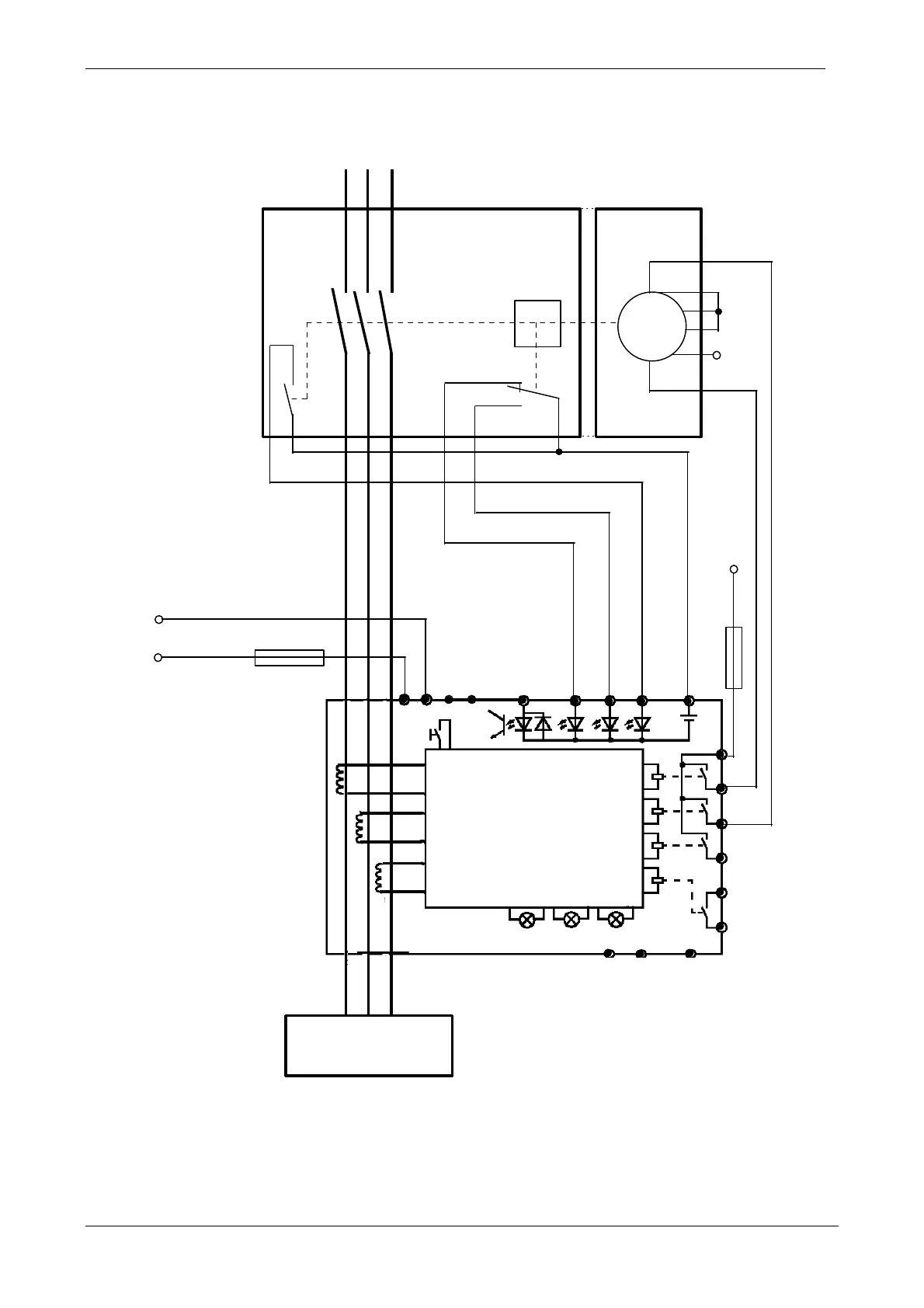
a.) Wiring diagram for connecting circuit-breakers 3VF3 - 3VF6 to SIMOCODE-DP:
M
111
112
113
114
N
M1
F1
A2
A1
AS
18
15
11
12
14
HS
A1 A2
1 2 3
4 5
F2
6
7
8
9
10
11
EIN
Motor
AUS
Motor
PROFIBUS-DP
Gen. Fault Bus Ready
PE
L1
L2 L3
115
AUS
116
EIN
T1 T2
NC
NC
3VF
AUS
3VF
EIN
TRIP +24V
3UF
3VF
Verbraucher
12
13
NC
NC
EIN = ON Verbraucher = load
AUS = OFF HS = auxiliary switch
NC = Not Connected AS = alarm switch
PE = potential earth

 Loading...