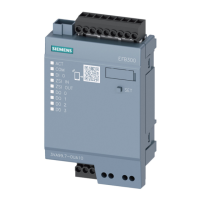
Communication System Manual 3WN6 Circuit-Breakers
Copyright Siemens AG 1998. All rights reserved. Version1.0 (05/98)
46
T-Nr. RELEASE N and P H and J/K D and E/F
Message address
1:8 Fault messages
32)
748, 1, 0
(Only with communication
module with measurement
functions (Z=F05))
The input of octet strings OS1 to OS4 is not
required for the message address in this case.
OS1:7
Underfrequency OS1:6
X
Overfrequency OS1:5
X
Reversal of direction of power
flow
OS1:4
X
Overvoltage OS1:3
X
Voltage phase imbalance OS1:2
X
Undervoltage OS1:1
X
Current phase imbalance
(Fine settings 5 - 50 %)
OS1:0
X
OS2:7
OS2:6
OS2:5
OS2:4
OS2:3
OS2:2
OS2:1
OS2:0
OS3:7
OS3:6
OS3:5
OS3:4
OS3:3
OS3:2
OS3:1
OS3:0
OS4:7
OS4:6
OS4:5
OS4:4
OS4:3
OS4:2
OS4:1
OS4:0
32)
"Fault signals" can refer to fault "Tripped" signals (OS1:2 of "additional functions 1“ (message number 1:121, page 50) = 1) or fault warning
signals (OS1:2 of "additional functions 1" = 0). Fault "Tripped" signals: These are registered as a group signal in OS4:2 of message 1:2
(parameter code 742, 1, 0) - see group signal tripping via fault messages, page 43. Fault warning signals: These are registered directly in the
group warning signal of the cyclic data.

 Loading...