Operating and display elements
2.2 Operating and display elements: CPU 31x
CPU 31xC and CPU 31x, Technical data
Manual, Edition 08/2004, A5E00105475-05
2-9
2.2.3 Operating and display elements: CPU 31x-2 PN/DP
Operating and display elements
RUN
STOP
MRES
BF1
SF
DC5V
FRCE
RUN
STOP
X1
LINK
RX
/
TX
MAC-ADD.:
X1-X2-X3
X4-X5-X6
X2
BF2
MMC
1 2 3
4
5
6
7
8
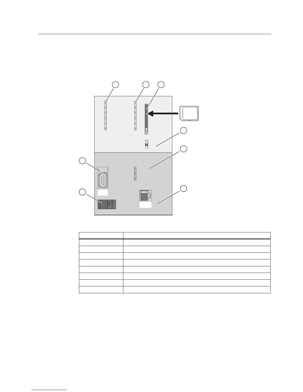
The figures show the following CPU elements
(1) Bus error indicators
(2) Status and error displays
(3) Slot for the Micro Memory Card (MMC), incl. the ejector
(4) Mode selector switch
(5) Status display of 2nd interface (X2)
(6) 2. Interface X2 (PN)
(7) Power supply connection
(8) 1. Interface X1 (MPI/DP)
 Loading...


