09.02 Start-Up
Siemens AG 6SE7087-6AK85-1AA0
4-63
Rectifier/Regenerating Unit Operating Instructions
x4
+
+1
+2
+3
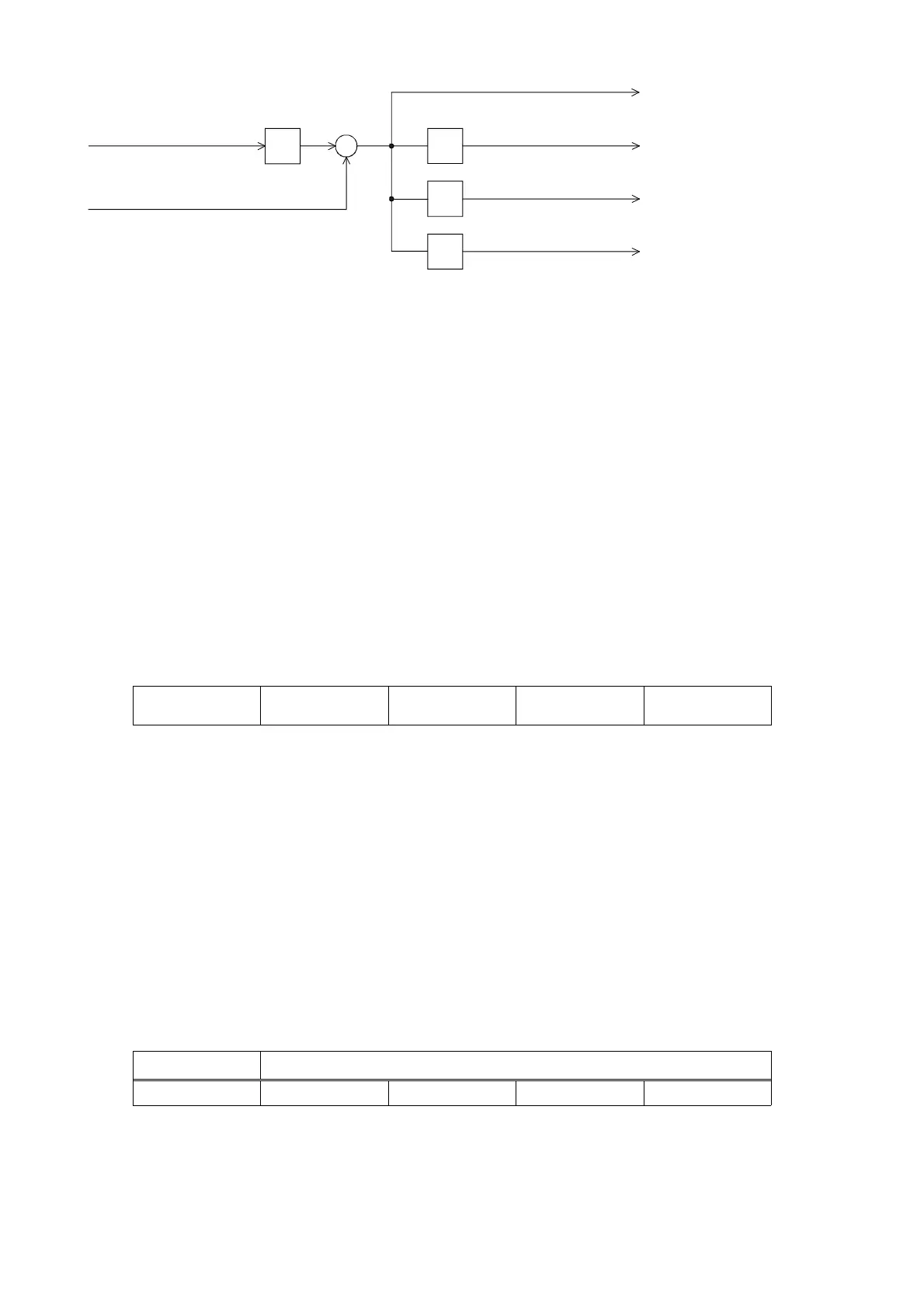
Node address
of drive (P918)
Basic identifier for
PZD send (U713)
PZD Send 2 (actual values 5 to 8)
PZD Send 1 (actual values 1 to 4)
PZD Send 3 (actual values 9 to 12)
PZD-Send 4 (actual values 13 to 16)
Example of PZD Send:
P918 = 1 This setting assigns identifier 200 to the first 4 send PZDs,
P698 = 196 identifier 201 to the second 4 send PZDs, etc.
How received data are utilized by the drive or which data are to be sent by the drive is determined by
connectors.
3 different modes of COB transmission can be selected in CB parameter 5 (P700):
P700 = 0 Actual values are transmitted only on request (Remote Transmission Requests)
P700 = 1 to 65534 Actual values are transmitted after the set time [ms] or on request (Remote
Transmission Requests)
P700 = 65535 Actual values are transmitted if the values have changed (event) or on request
(Remote Transmission Requests). This option should only be used in cases where
values seldom change so as to prevent excessive bus loading.
Structure of a telegram for PZD data exchange:
The telegram consists of the following data words:
Identifier
ID
Process data word 1
PZD1
Process data word 2
PZD2
Process data word 3
PZD3
Process data word 4
PZD4
ID is the CAN identifier that is defined for the COB in question by parameterization.
PZDx are process data words
Example of a PZD setpoint telegram:
Using the receive identifier of the above example
Receive identifier 140
d
008C
h
1. Setpoint 40063
d
9C7F
h
control word 1
2. Setpoint 8192
d
2000
h
50%
3. Setpoint 123
d
007B
h
4. Setpoint 0
d
0
h
Using the CAN BusAnalyser++ from Steinbeis, the setpoint data appear as follows (data field length = 8
bytes, low and high bytes are shown swapped round):
Identifier Data field
64 00 7F 9C 00 20 7B 00 00 00
ID PZD1 PZD2 PZD3 PZD4
AoteWell Automation Sales Team
Buy Siemens PLC HMI Drives at AoteWell.com
 Loading...