Connection 09.02
3-18 Siemens AG 6SE7087-6AK85-1AA0
Rectifier/Regenerating Unit Operating instructions
Function Terminal Connected loads/Description
Binary outputs X104-17
X104-18
X104-19
X104-20
Binary output 1, pin 1
Binary output 1, pin 2
Binary output 2, pin 1
Binary output 2, pin 2
The binary outputs are normally-open relay contacts
At 50V AC max. switching voltage, the following
applies:
Max. switching current 1A~ at p.f. =1
Max. switching current 0.12A AC at p.f. = 0.4
At max. 30V DC switching voltage, the following
applies::
Max. switching current 0.8A (resistive loads)
For functions see Section 4.3.3 and 4.3.1.2 (status
word)
Table 3.9 Control terminal block
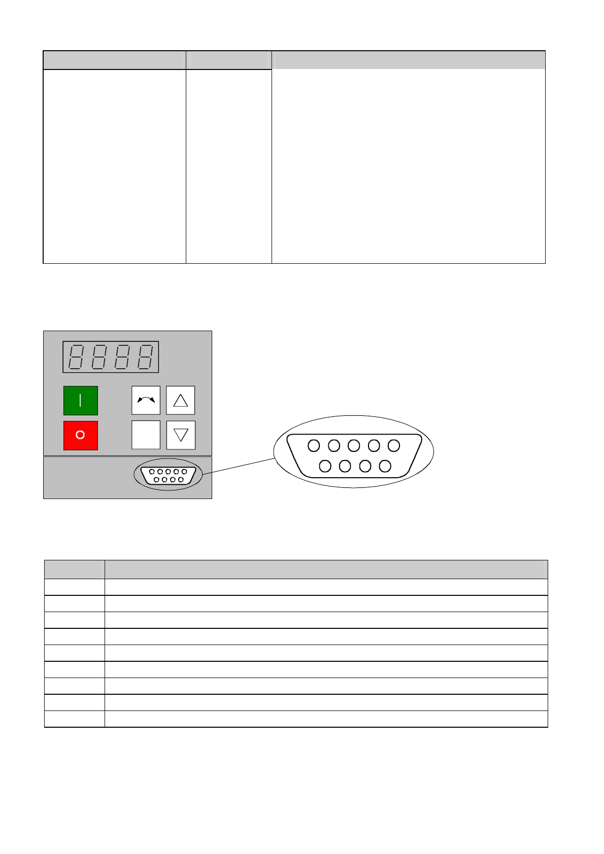
3.3.4 Connecting-up the parameterizing unit (PMU)
9
68
7
15234
X300
P
A serial connection to automation unit or a PC can be realized via
connector X300 on the PMU.The cables must be shielded and
connected to ground at both ends. (See Sec. 3.3.2). Thus,
the rectifier/regenerating unit can be controlled and operated from
the central control station or control room.
Figure 3.8 Parameterizing unit (PMU)
PMU -X300 Description
1 Housing ground
2 Receive line, RS232 standard (V.24)
3 Transmit- and receive line, RS485, two-wire, positive differential input/output
4 RTS (Request to send; for direction reversal in the case of interface converters
5 Ref. potential (ground)
6 5 V power supply for OP1S
7 Transmit line, RS232 standard (V.24)
8 Transmit- and receive line RS485, two-wire, negative differential input/output
9 Ref. potential for RS232 or RS485 interface
Table 3.10 Connector pin assignment for interface X300
AoteWell Automation Sales Team
Buy Siemens PLC HMI Drives at AoteWell.com
 Loading...