A 01/13 2-channel Binary Signal Transducer Page 21 of 40
s
Page 20 of 40 2-channel Binary Signal Transducer A 01/13
s
Explanation of the commands:
AT = If connected correctly the modem answers with
OK
&F = load factory settings
\E0 = No echoe
#F0 = Stabilization of performance speed
$SB19200 = Fixed baud rate to terminal device (RS232
interface)
$MB19200 = Fixed baud rate between modem-1 and modem-2
&E14 = Data compression deactivated
&E3 = Switch off flow control
&W0 = Save settings
Note:
Four-wire operated transmission was tested successfully with these
settings.
The baud rate chosen must also be adjusted at the two binary signal
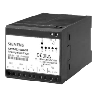
transducers (also see setting at binary transducer 7XV5653).
Connector and cable for four-wire leased line operation
For four-wire leased line operation use the supplied cables with the
imprint leased line. The RJ-11 connector is to be connected to the socket
marked with LEASED.
The other end of the cable is to be connected to a TAE-N coded telephone
outlet box as follows.
TAE-N 1
Tab.3: Connector and cable for four-wire leased line operation
• Initialization of the modems
The modems are to be initialized before commissioning.
This is best be done with the help of a terminal program, e.g. Hyper-
terminal.
- A null modem is needed for the connection between PC and
modem.
- Put in the following data into Hyperterminal and press ↵ to send
them to the modem. The modem will reply with OK.
For 19200 baud:
AT&FE0#F0$SB19200MB19200&E14&E3&W0↵
 Loading...