A 01/13 2-channel Binary Signal Transducer Page 27 of 40
s
Page 26 of 40 2-channel Binary Signal Transducer A 01/13
s
Terminal assignment
Pin Meaning Abbreviation
L+ Voltage supply L+ AC: L1 DC: L+
L- Voltage supply L- AC: N DC: L-
Pin 1 Fault signal relay contact M1 1 (NC contact)
Pin 2 Fault signal relay contact M1 2 (NC contact)
Pin 3 Command relay K1 3 (NO contact)
Pin 4 Command relay K1 4 (NO contact)
Pin 5- Binary input 1- BI-1-
Pin 6+ Binary input 1+ BI-1+
Pin 7- Binary input 2- BI-2-
Pin 8+ Binary input 2+ BI-2+
Pin 9 Command relay K2 9 (NO contact)
Pin 10 Command relay K2 10 (NO contact)
Tab. 4: Screw-type terminals
1.4 Description of the functional units
The signal converters inside the housing are hard-wired and tested
functional units. They are provided with a clip-on mounting for a DIN EN
50022 top-hat rail 35 mm. Auxiliary power supply can be safely connected
at the screw-type terminals. The FO channels are adapted via the ST-
terminals. The RS232 interface is connected via a 9-pole sub-D
socket. The devices are free of silicone and halogen as well as
flame-retardant.
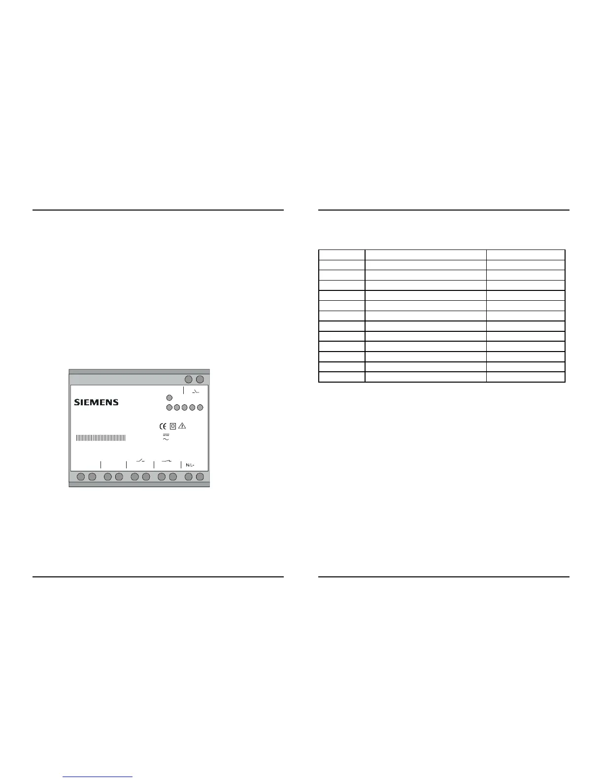
1.4.1 Position and assignment of the terminals
Fig. 3: Position and assignment of the terminals
8+ 46+ 27- 35- 1
L1/L+
10
K2
9
Binärsignalübertrager
7XV565 3-0BA0 0
SERIES: TDD-M2-450085
U
H
:
U
H
:
5
RUN
Bl-1
Bl-1Bl-2
Bl-2
K1
K1 M1
24-250 VDC/5W
60-230 VAC/5VA
(45-60 Hz)
K2
ERR
 Loading...