A 01/13 2-channel Binary Signal Transducer Page 33 of 40
s
Page 32 of 40 2-channel Binary Signal Transducer A 01/13
s
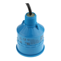
Fig. 5: Switching threshold of the binary inputs
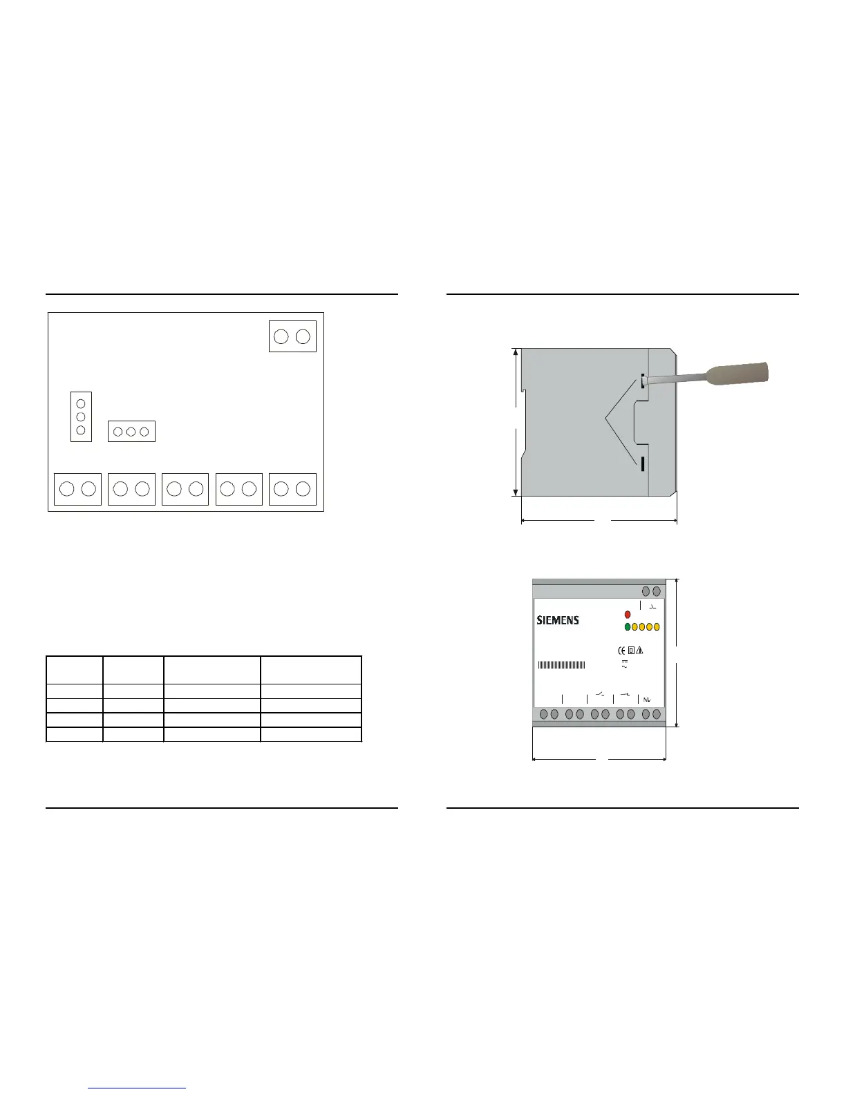
To change the jumper positions, the following instructions must be
observed:
• Disconnect the device
• Remove the cover of the housing
• with a small screwdriver, force the clips of the cover carefully
toward inside of the device
• change the jumper positions as shown in table 8
• snap the cover back into its position
Jumper Position Pick up
threshold
Binary inputs
X100
1-2
17 V 1 (BI-1)
X100 2-3 70 V 1 (BI-1)
X200
1-2
17 V 2 (BI-2)
X200 2-3 70 V 2 (BI-2)
Table 8: Switching threshold of the binary inputs
bold type = factory setting
X200
X100
1
1
105
95
8+ 46+ 2

 Loading...