A 01/13 2-channel Binary Signal Transducer Page 29 of 40
s
Page 28 of 40 2-channel Binary Signal Transducer A 01/13
s
Explanation
DIP switch (S1, S2)
Table 6: S1, DIP switch (2)
Bold type = factory setting
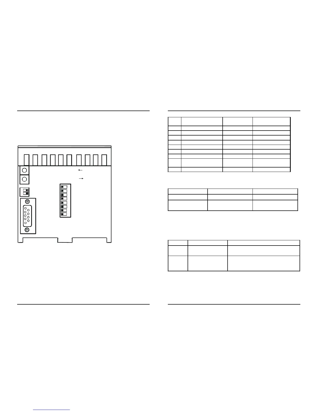
1.4.2 Switch positions and RS232 interface
The DIP switches can be operated from outside.
Position of the DIP-Schalter: View from the front
1
2
S1
FO receiver ST input •
FO transmitter ST output •
8
7
6
5
4
3
2
1
S2
X1
ON OFF
OFF ON
Fig. 4: Positions of the switches
Pin Description Abbreviation Direction as
DTE
1 - - No connection
2 Receive data RxD
In
←
3 Transmit data TxD
Out
→
4 - - No connection
5 Signal ground GND -
6 - - -
7 Signal ground GND -
8 Active interface
selection
Bridge Input
9 - - -
Switch Meaning Remark
Not connected FO connection active Pin 8 open
Factory setting is
FO connection
RS232 connection
active
Bridge pin 8 – 7
At the converter input
Switch Position Meaning
1
Open = off
Closed = on
Light off in idle state: FO receiving
Light on in idle state: FO receiving
2
Open = off
Closed = on
Light off in idle state: FO
transmitting
Light on in idle state: FO transmitting
Table 5: RS232 interface, 9-pole sub-D socket
 Loading...