A 01/13 2-channel Binary Signal Transducer Page 31 of 40
s
Page 30 of 40 2-channel Binary Signal Transducer A 01/13
s
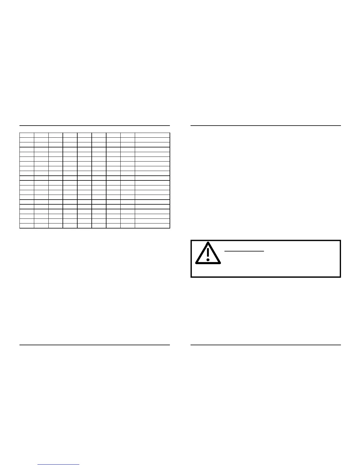
Table 7: S2, DIP switches (8)
bold type = factory setting
Explanation:
8E1 = 8 data, even parity, 1 stop bit
8N1 = 8 data, no parity, 1 stop bit
Testmode on:
The binary signal transducer runs a self-test. If the binary input is activated
(voltage impressed) the binary LED lights up (BI-1 or BI-2) and the
corresponding relay (K1 or K2) with associated LED (K1 or K2) is activated.
The diagnosis of the memory test and the position of the DIP switches
are put out on the serial interface (RS232) and can be displayed with a
terminal programm, running on a PC.
DIP 8 DIP 7 DIP 6 DIP 5 DIP 4 DIP 3 DIP 2 DIP 1
Setting of the baud rate via S2:
The baud rate (position of the DIP switches) is queried once after the
switching on. During active testmode the baud rate is queried
continuously and set anew.
Baud rate during operation: set baud rate via DIP switch 0..2, shortly
switch on and off DIP switch 6 (testmode).
Pitch up threshold of the binary inputs
Testmode off: The binary signal transducer is ready for normal operation.
Block MA: Block message outputs, the relays are not controlled.
Enable MA: Normal operation, message outputs are not put out.
Transmitter only:The binary signal transducer acts as transmitter only.
Missing incoming signals are not reported as comm. errors.
THE DEVICE MUST NOT BE OPERATED WHEN OPEN.
Remove Powersupply in this case!
Warning !
To change the threshold of the binary inputs the binary signal transducer
has to be opened and jumpers have to be changed.
 Loading...