e1276e
34
Siemens Building Technologies
Cerberus Division
09.2000
6.3 Electronic alignment
Switch to «AUTO-RANGE».
With the knurled screws fine-adjust the detector lens to the maximum signal (adjust-
ment set display switched to «RANGE»).
The knurled screws should be turned slowly in order to avoid large signal jumps.
When the maximum value is obtained (must be between min. 4 and max. 13), switch to
«FIX-RANGE» and adjust to the maximum value «SIGNAL». Caution! If the signal val-
ue is >60, switch back to «AUTO-RANGE» in order to adjust the range, and then re-
adjust to the maximum value «SIGNAL».
The «RANGE» and «SIGNAL» indication on the adjustment device should both be at-
tain a maximum value. If «Range» is 13 and «Signal» ≥60, the transmitter signal
(switch S3) must be set to weak.
Engage the locking screws.
Switch the adjustment set to «FIX-RANGE».
Cover the reflector.
With a dark cover interrupt the IR beam: the signal should decrease to <2. If this is not
the case the detector has not been aligned correctly to the reflector but to reflecting ob-
stacles in the environment of the measurement section. Repeat the adjustment proce-
dure!
Disconnect the adjustment set from the detector.
Reinstall the detector cover.
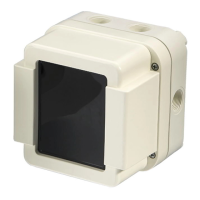
Connection adjustment set
 Loading...
