e1485b
4
Fire & Security Products
Siemens Building Technologies Group
06.2001
3 Principle of operation
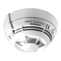
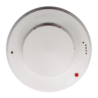
OptoRex DO1101-Ex
The OptoRex DO1101-Ex is based on the principle that
smoke scatters light. An infrared LED (IRED) transmits
brief, intensive light pulses into the scattering chamber.
The receiving element is screened off from direct IR light
incidence and reflections. Smoke entering the chamber
scatters the light so that some of it reaches the receiver
whose signal is evaluated by the electronics. After three
positively evaluated pulses an alarm is transmitted to the
control unit.
Time base
2
in the integrated circuit
1
controls the logic
unit
3
and produces pulses for controlling the IRED light
source
5
via the amplifier
4
. If the detector is not contami-
nated and the air is clean, no signal is available at the re-
ceiver
6
.
If the air contains smoke, the receiver sees a signal that is
transmitted via the amplifier
7
to the discriminator
9
. Inte-
grated in the amplifier is a multiple coincidence circuit that
generates the difference between a light and a dark mea-
surement which has the effect that no interference signals
and «only» smoke induced signals are amplified and trans-
mitted. In circuit
8
a stable reference voltage U
aref
is pro-
duced which in discriminator
9
forms the alarm threshold.
The detector sensitivity is set with the trimming resistor
10
.
The signal voltage U
sig
at the output of the receiving ampli-
fier can only be factory-measured with the aid of special
measuring equipment. The alarm threshold U
aref
is used
for measuring the alarm stroke ∆
U3A
on site with the detec-
tor measuring instrument DZ1194.
The logic unit
3
evaluates the pulses of discriminator
9
and after the third pulse activates the alarm stage
11
inte-
grated in ASIC. Also activated in the event of an alarm are
the internal response indicator
12
and an external response
indicator
13
if available. The alarm stage
11
is self-holding
and is restored to the initial condition only when reset by the
system control unit (through brief interruption of the operat-
ing voltage). The intrinsically safe detector circuit is iso-
lated from the line circuit by protective diodes
14
.
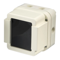
ThermoRex DT1101-Ex / DT1102-Ex
The ThermoRex DT1101/DT1102 measures the ambient
temperature with the NTC thermistor R
m
in the tip of the
sensor and measures the temperature in the detector
housing with the NTC thermistor R
g
. Rapid temperature
changes bring about a faster change of resistance with
thermistor R
m
than with thermistor R
g
. This causes a posi-
tive voltage shift at point P. As soon as this voltage exceeds
a fixed threshold value, the threshold value detector
3
acti-
vates multivibrator
4
and an alarm is given. If, due to a very
slow increase in temperature, the resistance values R
m
and R
g
fall to the same extent, upon reaching a maximum
temperature determined by resistors
1
and
2
an alarm is
given. At the same time resistor
2
accelerates response
for fast changes in temperature.
The weak current I
B
flows in non-alarm condition. As soon
as the multivibrator
4
becomes conductive, the response
indicator alarm current I
A
flows. At the same time the re-
sponse indicator
6
built into the detector is activated via
the driver stage
5
. One external response indicator
7
may
be connected. The multivibrator remains in self-hold condi-
tion until the control unit is reset by briefly interrupting the
operating voltage, whereupon it reverts to its original state.
The intrinsically safe detector circuit is isolated from the line
circuit by protective diodes
8
.
Operating voltage
Shunt Zener
diode barrier
Detector
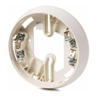
Base
Shunt Zener
diode barrier
+
–
Detector
Base
5 6
4
8
7 9
3
2
11
10
U
aref
U
sig
1
12 13
C
A
U
B
E
F
D
B
∆
U3A
ASIC
14
Operating voltage
1
+
–
6
5
3
2
C
A
U
B
E
F
D
B
4
R
m
R
g
7
I
A
I
B
P
MB
8
Fig. 1 Block diagram DO1101-Ex Fig. 2 Block diagram DT1101-Ex/DT1102-Ex
 Loading...