Installation, connecting up, commissioning
3.2 Installing, connecting up and commissioning
CP 1243-1
Operating Instructions, 04/2017, C79000-G8976-C365-03
35
Table 3- 1 Dimensions for installation (mm)
CPU (examples)
CPU 1214C 110 mm 55 mm
Communications inter-
faces (examples)
CM 1241, CM 1243-5, CM 1242-5
CP 1242-7, CP 1243-1, CP 1243-7, CP 1243-8 IRC 30 mm 15 mm
* Width B: The distance between the edge of the housing and the center of the hole in the DIN rail mounting clip
You will find detailed dimensions of the module in the section Dimension drawings
(Page 139).
DIN rail clamps, control panel installation
All CPUs, SMs, CMs and CPs can be installed on the 35 mm DIN rail in the cabinet. Use the
pull-out DIN rail mounting clips to secure the device to the rail. These mounting clips also
lock into place when they are extended to allow the device to be installed in a switching
panel. The inner dimension of the hole for the DIN rail mounting clips is 4.3 mm.
The module must be installed so that its upper and lower ventilation slits are not covered,
allowing adequate ventilation. Above and below the device, there must be a clearance of 25
mm to allow air to circulate and prevent overheating.
Remember that the permitted temperature ranges depend on the position of the installed
device. You will find the permitted temperature ranges in the section Technical
specifications of the CP 1243-1 (Page 133).
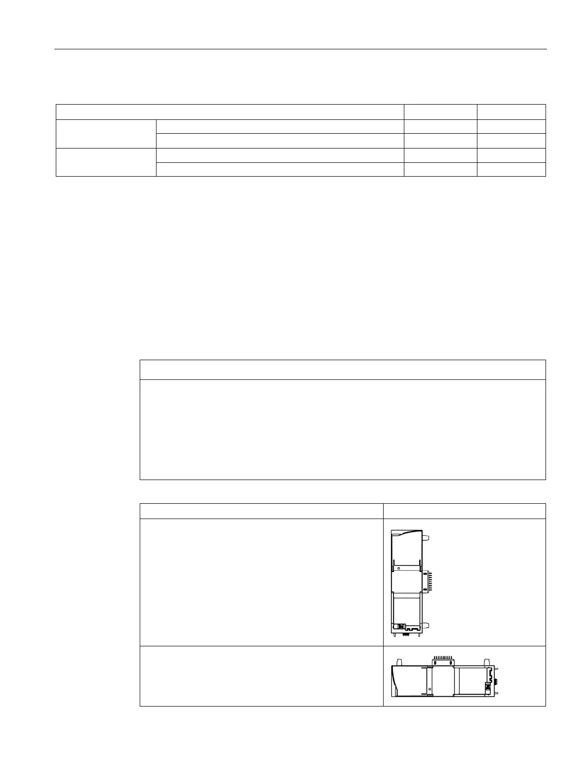
Device position / permitted temperature range
Horizontal installation of the rack
Vertical installation of the rack:
 Loading...