Description of the device
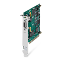
1.3 PROFIBUS interface
CP 5623/CP 5624
12 Operating Instructions, 09/2013, C79000-G8976-C281-03
The physical link between the PROFIBUS interface and the PROFIBUS network is via a
floating RS-485 interface that is part of the module. Depending on the network configuration,
data rates of 9.6 Kbps up to a maximum of 12 Mbps are possible in the PROFIBUS network.
Note
You will find information about the structure of a PROFIBUS net
work in the system manual
"PROFIBUS Network Manual". The document is part of the Manual Collection. You will also
find this on the Product Support pages under the following entry ID:
http://support.automation.siemens.com/WW/view/en/35222591)
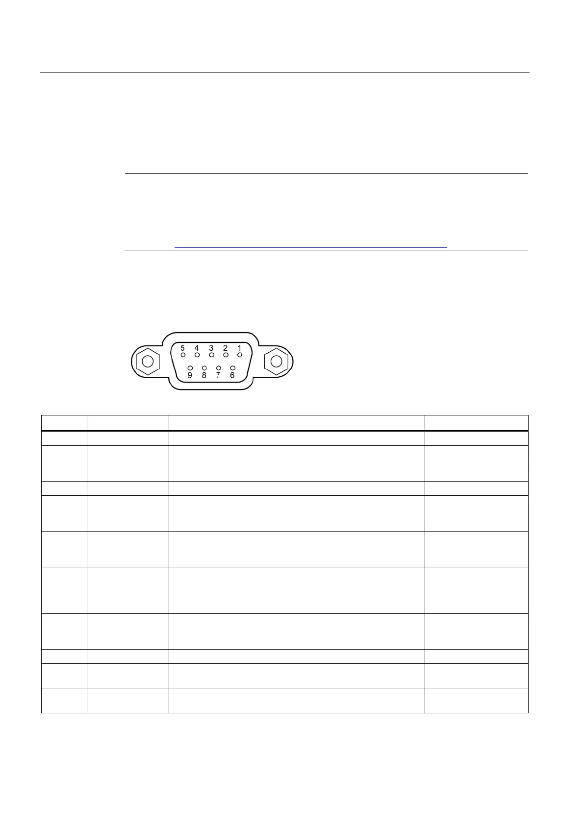
The D-sub female connector has the following pin assignment:
Socket pin 1 is not connected.
2 NC (M24) Socket pin 2 is not connected. With other MPI/DP components,
the return line of the floating 24 V power supply may be via this
-
Signal line B of the PROFIBUS connector.
4 RTSAS RTSAS, input signal for direct MPI link. The control signal is "1"
active when the automation system connected over a special
MPI cable is sending.
Input
5 M5EXT M5EXT return line (GND) of the 5 V power supply. The current
load of an external consumer connected between P5EXT and
M5EXT must not exceed a maximum of 90 mA.
Output
6 P5EXT P5EXT supply (+5 V) of the 5 V power supply. The current load
of an external consumer connected between P5EXT and
M5EXT must not exceed a maximum of 90 mA (short-circuit
Output
7 NC (P24V) Socket pin 7 is not connected. With other MPI/DP components,
the P24V supply of the floating 24 V power supply may be via
-
Signal line A of the PROFIBUS connector.
9 RTS RTS output signal of the CP module. The control signal is "1"
active when the device (PG or PC) is sending.
Output
Shield The shield is connected to components of the connector
 Loading...