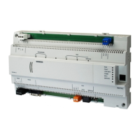
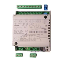
Technical and mechanical design
The compact build allows for mounting the devices on a standard rail or a wall.
1
2
3
4
5
6
7
8
910
11 12
13
14
15 16
Date/Series
S/N
WLAN
Default
10
11
Service button (network login and WLAN on/off)
2-port Ethernet switch with 2 LEDs per port for
display purposes
Plug-in terminal block with screw terminals
KNX, PL-link, for future use
Plug-in terminal block with screw terminals
Power supply
Plug-in terminal blocks with screw terminals
Digital input, for future use
Plug-in terminal block with screw terminals
M-bus, for future use
Plug-in terminal block with screw terminals
COM1 / COM2 (MS/TP or Modbus)
DIP switches for bus termination and polarization
COM1 / COM2
Slider for mounting on standard mounting rails
Date / Series and Serial number
LEDs for communication and state
QR code for default WLAN access
Description see Technical data
Continuously ON
Continuously OFF
Flashing
Link active
No connection
Network traffic
Continuously ON
Continuously OFF
Link 100 Mbps
Link 10 Mbps
Continuously ON
Continuously OFF
Flashing
Device operational
Device not operational
Start-up or program halted
Continuously OFF
Continuously ON
Rapid flashing
OK
HW or SW fault
Firmware or application missing/corrupted
Continuously ON
Continuously OFF
Connection to the cloud OK
No connection to the cloud
Continuously OFF
Continuously ON
Optional battery OK
Optional battery empty - replace
Flashing
Continuously OFF
Communication
No communication to subsystem
Continuously OFF
Flashing
OK
Device is not configured
Flashing per wink
command
Identification of the device after receipt of
wink command