Insulation and Contact Resistance Test
Refer to Circuit Breaker Operator Manual
E50001-
F710-A251-V3-4A00.
Inspection and Cleaning of Circuit Breaker Insulation
Refer to Circuit Breaker Operator Manual E50001-
F710- A251-V3-4A00.
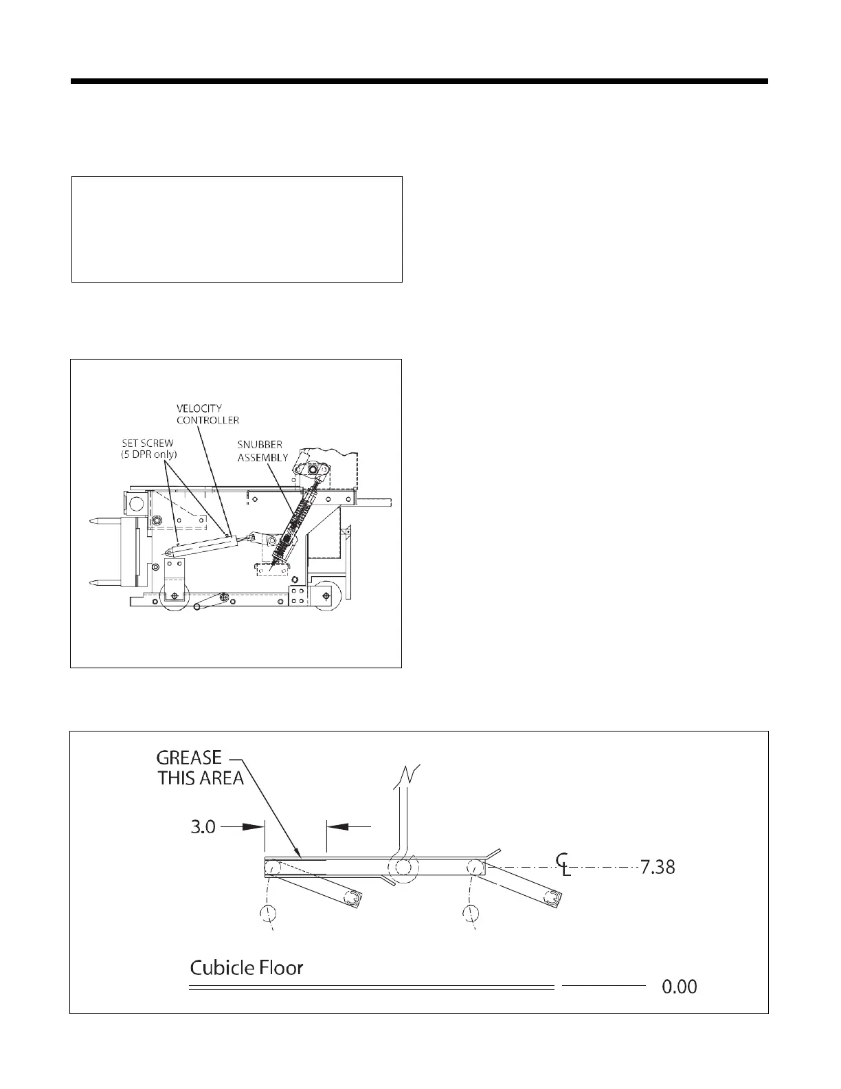
Figure 6.
Velocity Controller and Snubber Assembly
Racking Mechanism
Remove existing lubricant from racking mechanism. Ap-
ply Klueber Isoflex Topas L 32 lubrication (part #
3AX11333H.) to the slid- ing, rotating and articulating
surfaces. For inaccessible surfaces, Klueber Isoflex
Topas L32N SPRAY LUBE (part # 15-172-879-201) may
be used.
MOC Actuator System
Refer to Figure 6 & 7.
MOC actuator system shall be maintained and lubricated
as following:
1.
Visually inspect to confirm that the velocity controller
is not leaking oil.
2.
Verify that both setscrews on the velocity controller are
tight (5 DPR only).
3.
Verify velocity controller rod resistance. Remove
shoulder bolt, washer and stop nut, and verify rod
resistance by pushing rod “in” and “out”. Re-assemble
the velocity controller assembly.
4.
Check snubber for visual damage (broken clips and
loose hardware).
5.
Verify and adjust cubicle MOC components as needed
to match pantograph reference dimensions shown in
Figure 7
.
6.
Lubricate cubicle pantograph. Apply Klueber Isoflex
Topas L 32 lubrication (part # 3AX11333H..) to
pantograph area of MOC actuator pin interface
(CONNECT and TEST (if available) positions).
Maintenance of the circuit breaker MOC actuator system
DOES NOT mitigate the requirements to maintain cubicle
mounted MOC system components. These shall be main-
tained in accordance with IEEE C37.59 and the original
equipment manufacturer’s recommendations.
Figure 7.
Cubicle Pantograph Setup
Note:
Maximum Contact Resistance is read from
primary bus stab to primary bus stab with primary
disconnects removed. A value of 13 micro-ohms
should be added to the maximum contact resistance
specified in the Circuit Breaker Operator Manual
E50001-F710-A251-V3-4A00.
 Loading...