Functional Tests
Refer to Circuit Breaker Operator Manual
E50001-F710-
A251-V3-4A00.
Periodic Maintenance Intervals
Refer to Circuit Breaker Operator Manual
E50001-F710-
A251-V3-4A00
and
Table 3
.
Table 3 — Periodic Lubrication Interval
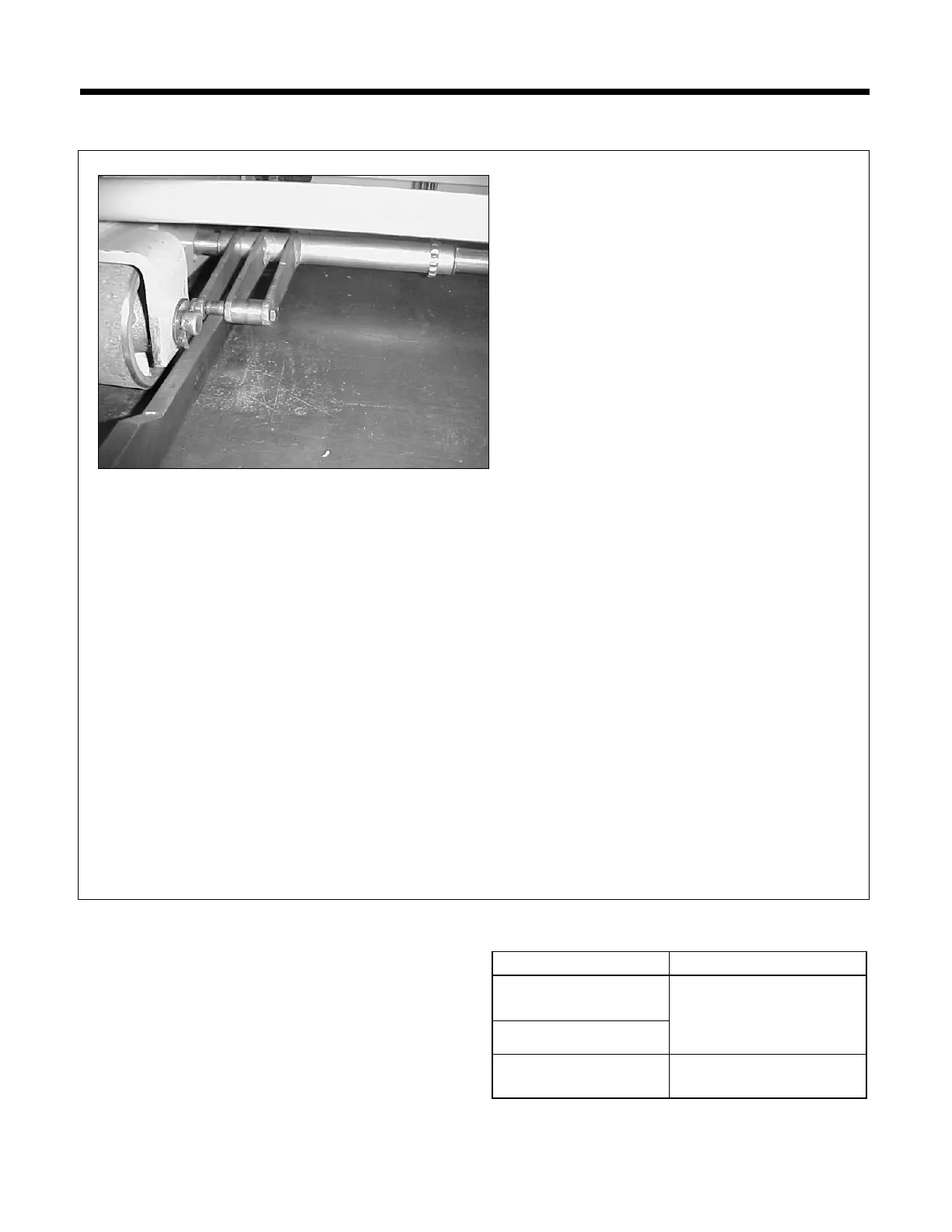
Step 7
Roll the circuit breaker trip roller (smaller roller
located towards the outer edge of the circuit
breaker) onto the 0.70 inch step of the adjustment
tool.
Step 8
Charge circuit breaker closing spring until it is
latched and closing spring indicator reads
CHARGED.
Step 9
Attempt to close the circuit breaker by pressing
the black close button on the front of the circuit
breaker.
Verify that circuit breaker is trip-free (closing spring
will discharge but circuit breaker jackshaft should
not rotate).
Step 10
To ensure proper adjustment of the Floor Interlock
and Operating Lever repeat steps 3 to 9 a mini-
mum of 2 times.
If the results cannot be achieved, loosen the hex-
jam nut on the 3/8 inch rod of the indicated clevis
with the 9/16 inch wrench and turn the rod half a
turn counterclockwise. Tighten hex-jam nut, then
repeat steps 3 through 9.
If the expected results in steps 3 through 9 still
cannot be obtained, repeat step 10 until steps 3
through 9 can be successfully completed.
Note: The minimum height of the spring discharge
interlock roller (large roller) from the floor shall
not be less than 0.05 inches with the roller having
some resistance to rotation but still able to be ro-
tated manually.
Primary Disconnect
contact surfaces
100 racking operations
or 10 years
Racking Mechanism
MOC Actuator System
10,000 operations or 10
 Loading...