The closing spring, if charged, will automatically discharge
when the circuit breaker is withdrawn from the switchgear.
The circuit breaker may open and its closing spring may
discharge as it is withdrawn from the cubicle. It depends
on whether the circuit breaker was left closed or open, or
whether the spring was left charged or discharged.
Automatic Floor Tripping and Closing Spring Release
The Floor Interlock and Automatic Tripping Lever activates
the tripping trigger as the circuit breaker is withdrawn from
the cubicle Test position. This, together with the automatic
floor closing spring release, acts to discharge the closing
spring and trips the circuit breaker as it is withdrawn from
the cubicle.
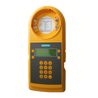
Secondary Contacts
The 15 point secondary contact block is mounted on a
slideable plate on the inside of the left hand chassis side
plate. This sliding plate is operated by a round folding rod
with a “T” handle, extending from the L.H. upper corner
of the mechanism panel. Above this rod is the secondary
contact levering handle. When the circuit breaker is in the
TEST position, the secondary contact block is normally dis-
connected and in the forward position against the rear of
the chassis.
When you wish to operate the circuit breaker electrically
while it is in the TEST position, the folding rod is lifted to
the horizontal position enough to unhook it from the panel,
and then pushed to the rear until the cross-pin engages
with the slots of the levering handle, as shown in
Figure 3.
The handle is then pressed down to make final engage-
ment of the secondary contacts.
Figure 3.
Secondary Contact Operation
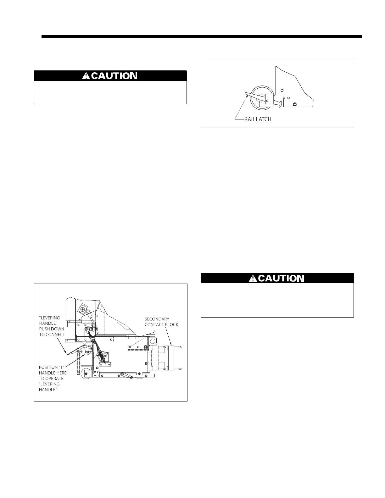
Rail Latch (Figure 4)
The purpose of the rail latch is as follows.
1.
The rail latch prevents accidental damage to the cubicle
levering device screw or the levering-in nut on the cir-
cuit breaker. Without this rail latch, the levering device
screw and possibly the levering-in nut would be dam-
Figure 4. Rail Latch
aged if the circuit breaker were pushed into the cubicle
so as to bump the levering-in nut hard against the end
of the levering device screw.
2.
The rail latch holds the circuit breaker in the TEST posi-
tion. In order to lever the circuit breaker in to the CON-
NECTED position, press down rail latch (conveniently
performed by foot) and push the circuit breaker 1/4 to 3/
8 inch so as to get the levering device nut against the
screw.
Continuous Current Interlock
The continuous current interlock functions to ensure circuit
breaker and cubicle of like continuous current ratings are
applied, and that circuit breakers with dissimilar continuous
current ratings are excluded from cubicles of unlike current
ratings.
Removing Circuit Breaker from Cubicle
To remove the circuit breaker from the operating position,
trip the circuit breaker open, and engage the levering crank
on the levering device shaft. Turn the crank counterclock-
wise until the crank rotates freely. Pull the circuit breaker
toward the front of the cubicle until the rail latch engages
the slot in the rail. The circuit breaker is now secured in the
TEST position.
To remove the circuit breaker from the cubicle, press down
on the rail latch to free the circuit breaker from the rail.
Pull the circuit breaker out of the cubicle.
Control Cable Box
The type DPR circuit breaker employs a plug-in cable which
completes circuit breaker electrical connections between the
mechanism housing and the vehicle’s secondary disconnects.
Insulating Barriers
Insulating barriers are required for use on type DPR circuit
breakers.
Interphase and exterior barriers are removed or inserted
vertically and are bolted to vehicle assembly.
 Loading...