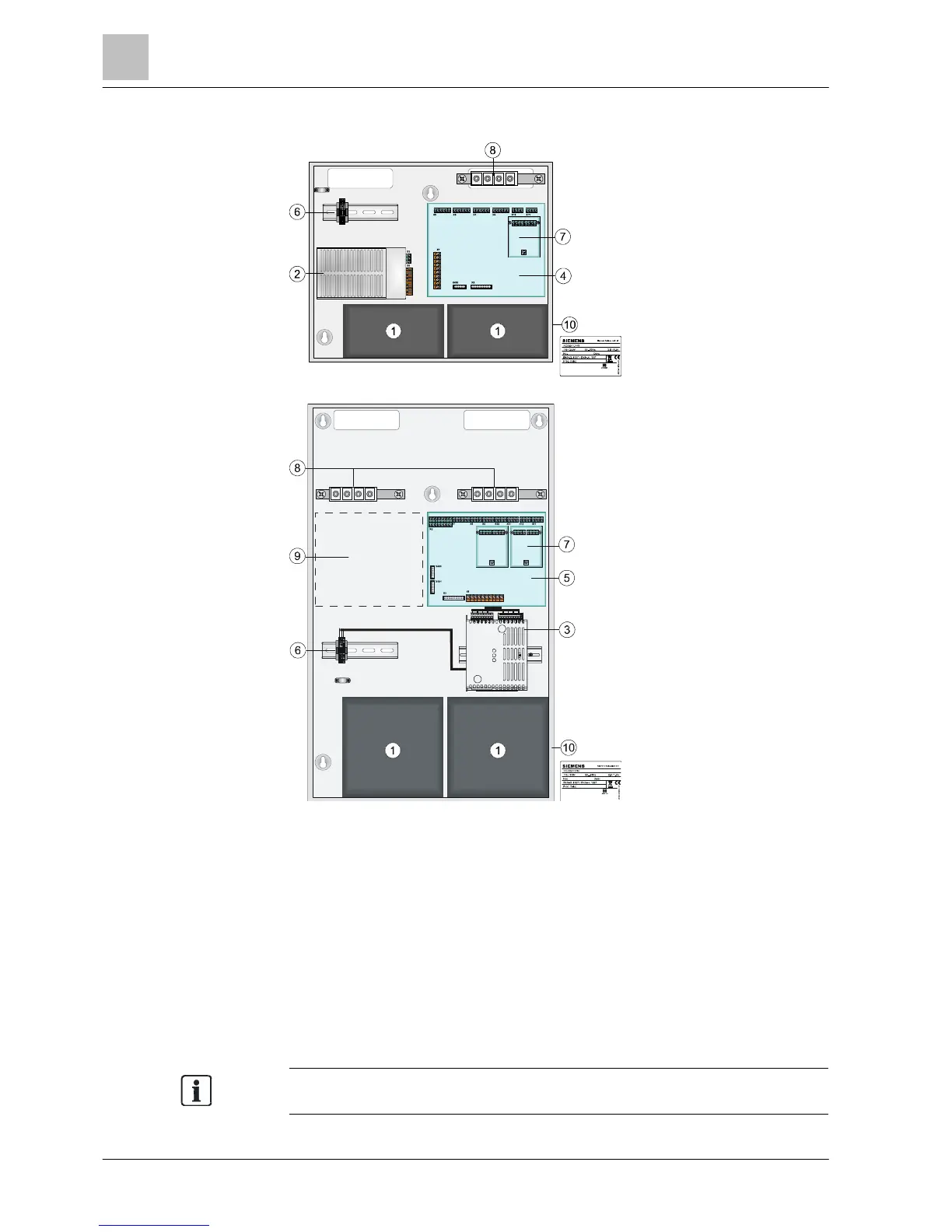
5.1 Position of printed circuit boards / components
Figure 2: Position of components in housing (Standard) for FC722
Figure 3: Position of components in housing (Comfort) for FC722 or FC724
1 Batteries 6 Mains connection terminals (L1,N,PE)
2 Power supply (70 W) 7 Loop extension option (C-NET) 1 x for FC722, 2 x for FC724
3 Power supply (150 W) 8
Shield connection terminal blocks or cable kit option
(communication)
4 Periphery board (2 loops) 9 Space for more options, e.g. fire brigade periphery module
5
Periphery board (2 loops or 4
loops)
10 Type plate
You will find further information on removing the FC722 and FC724 stations and
the housings and options available in the system documentation.