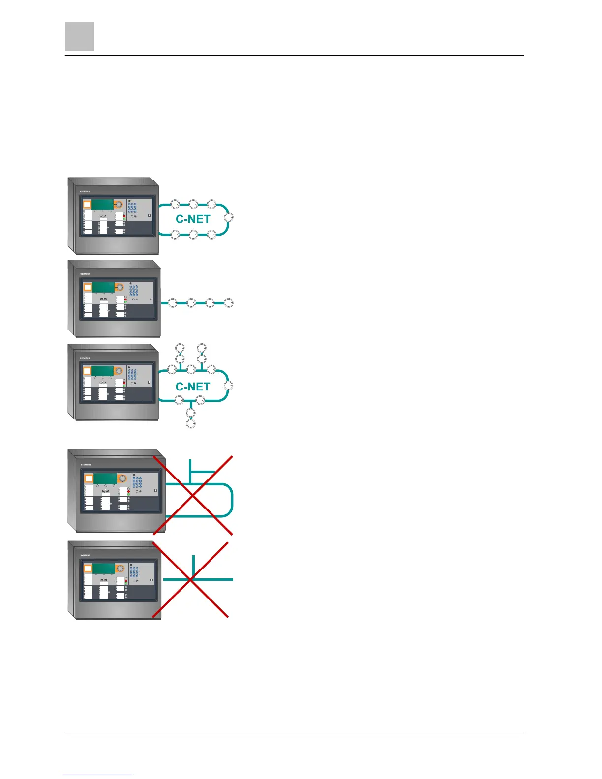
5.6 C-NET topology and connection
Permissible topology for the C-NET
The C-NET can only be wired in the topologies shown below. Regardless of the
topology (loop, stub or loop with sub-stub), the C-NET system limits, such as
length, cable resistor, number of line devices etc., must be observed.
Either one loop or two stubs can be connected to a C-NET line connection (2-wire
line on block of 4 terminals).
Loop
(max. 1 loop per line connection)
Stub line
(max. two stubs per line connection)
Sub-stubs on loop
A sub-stub may only be connected between two line devices and/or
line separators, and directly on the terminal connection.
Wiring NOT admissible
NOT admissible!
Sub-stub on sub-stub
NOT admissible!
Sub-stub on a stub
The connection terminals for the C-NET are located on the periphery board or on
the loop extension (C-NET).