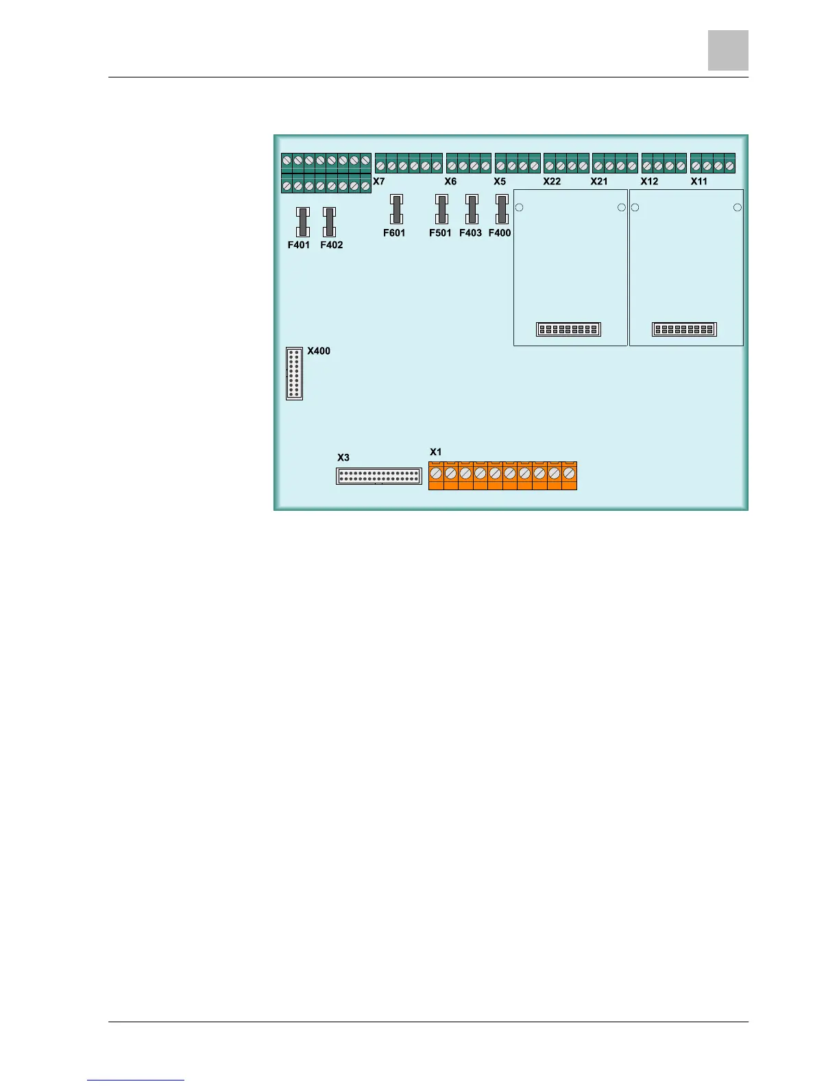
Position of connection terminals on periphery board (4-loop) of
FC724 fire control panel
Figure 8: Periphery board (4-loop) for FC724
X1 Connection of power unit X11 C-NET loop 1 or stub 1+2
X3
Ribbon cable to PMI & mainboard (operating unit on pivot
frame)
X12 C-NET loop 2 or stub 3+4
X5 Monitored outputs for acoustic signal transmitter X15 2 x C-NET loop extension
X6 Monitored outputs for alarm and fault messages X21 C-NET loop 3 or stub 5+6
X7
Changeover contacts for RT Alarm and RT Fault (remote
transmission)
X22 C-NET loop 4 or stub 7+8
X8/1 Configurable inputs/outputs (1-8), supply voltage Vsys 1 X400
Ribbon cable peripheral data
bus
X8/2 Configurable inputs/outputs (9-16), supply voltage Vsys 2 Fxxx SMD fuses 1A/T
More details of the periphery board can be found in the 'System documentation'.
X8/2
X8/1