EasyManuals Logo

Siemens FC924 Installation Instructions

Siemens FC924
28 pages
To Next Page IconTo Next Page
To Previous Page IconTo Previous Page
Page #16 background imageLoading...
Page #16 background image
16
Siemens Industry, Inc. A6V10356958_en--_n
Smart Infrastructure
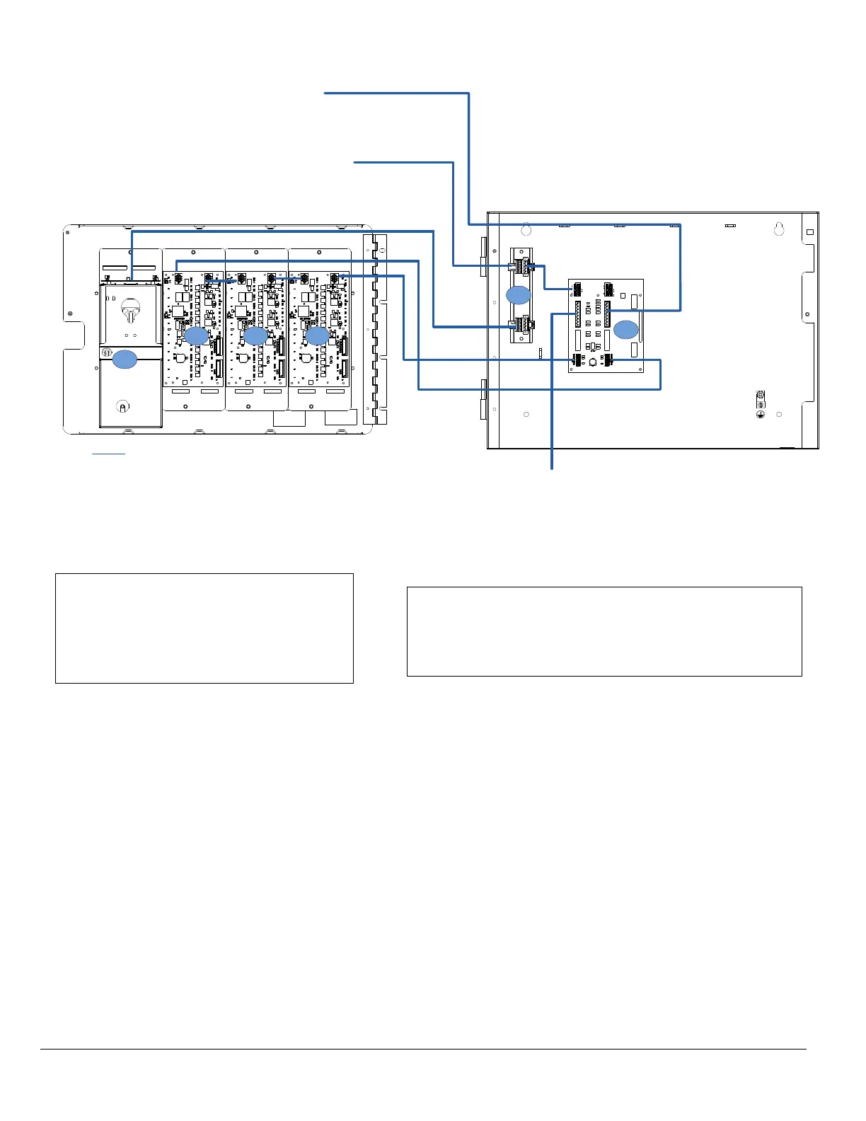
Figure 4: Module Location in 1HU Remote Microphone Station and Recommended Wire Routing
Module
Locations
:
1. VTO2004-U2/U3
2. VTO2001-U2/U3
3. VTA2001- A1
4. FHA2031-U1 (optional)
Recommended Wiring Routes:
Any knockouts may be used for the power-limited wiring
associated with the Remote Microphone.
TO FV922/FV924 FIRE VOICE CONTROL
PANEL OR ADJACENT VR2005
REMOTE MICROPHONE STATION
TO ADJACENT VR2005 REMOTE
MICROPHONE STATION
TO MUTED SPEAKER
1
2
3
4
POWER LIMITED
Knockout
# 1
Knockout # 2
2 2

Other manuals for Siemens FC924

Questions and Answers:

Question and Answer IconNeed help?

Do you have a question about the Siemens FC924 and is the answer not in the manual?

Siemens FC924 Specifications

General IconGeneral
BrandSiemens
ModelFC924
CategoryControl Panel
LanguageEnglish

Related product manuals