Siemens Industry, Inc. A6V10356958_en--_n
Smart Infrastructure
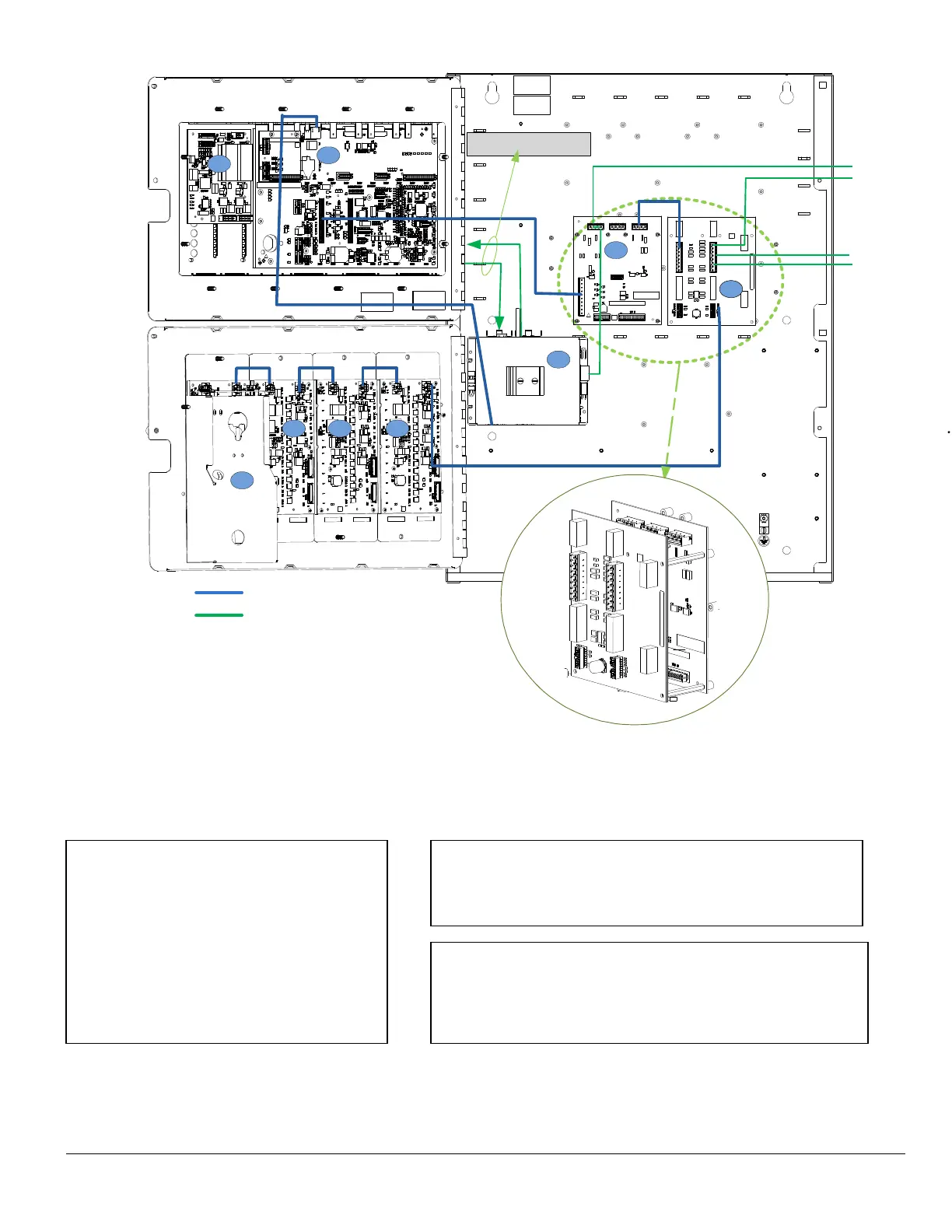
Figure 5: Module Location for 2HU Enclosure (Remote Station) and Recommend Wiring Routing
1. FCM2018-U3 / FCM2019-U3
2. FCA2015-U1 (optional)
3. FTI2001-U1
4. VTA2001-A1
5. FN2012-A1 with VN2001-A1 / VN2002-A1
/ VN2003-A1
6. VTO2004-U2/U3
7. VTO2002-U2/U3
Recommended Wiring Routes:
Any knockouts may be used for the power-limited wiring
associated with the 2HU - Remote Station.
As indicated in Figure 5, FTI2001-U1 and VTA2001-A1 are
stacked on top of one another using the standoff provided with
VTA2001-A1. It is shown flat for ease of layout.
1
2
3
4
5
6
777
To FV922 / FV924
24VDC
Low Level
Audio
CAN Bus
Internal Wiring
External Wiring
 Loading...


