Siemens Industry, Inc.
Building Technologies Division
A6V10315044_enUS_c4
WIRING
Remove all system power before installation, first battery then AC. (To power up,
connect the AC first, then the battery.)
The PAL-1 is connected to the FCA2018-U1 with a standard PC printer cable. This
cable is supplied with the FCA2018-U1. Connect the PAL-1 to the FCA2018-U1 using
this cable. The two ends of the cable are different, ensuring proper connection. See
Figure 4.
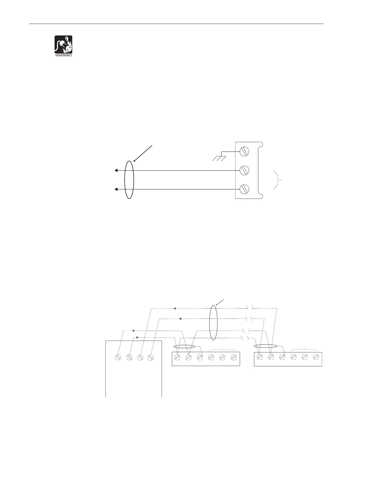
The FCA2018-U1 requires 24VDC to operate. This power is available on the Aux
Power Terminal (X1001) on the FS20 Periboard. See Figure 5 for wiring details.
Figure 5
Connecting Power To The FCA2018-U1
NOTES:
1. 18 AWG min., 12 AWG max.
2. Power limited to NFPA72
per NEC 760.
3. No end of line device
required.
4. 50Ω max. total wire
resistance.
5. Refer to FS20 Product Data
Manual, P/N A6V10315015,
for ground fault detection
impedance.
+
_
CHASSIS GROUND
24V INPUT
1
2
3
TO FC360, X1_N
SUPERVISED &
POWER LIMITED
TO FC360, X1_P
The FCA2018-U1 can be connected to the UFP Style 6 or Style 4. Refer to the FS20
configuration for the proper Style. If the FCA2018-U1 is connected at the end, care
must be taken to properly terminate the UFP. See Figure 6 for the wiring instructions
when the FCA2018-U1 is connected as Style 6 and Figure 7 when the FCA2018-U1 is
connected as Style 4.
12 3 45 6
SHIELD
FCA2018-U1 UFP
TERMINAL BLOCK
12 3 4
5
6
SHIELD
FCA2018-U1 UFP
TERMINAL BLOCK
FC2016-U1
RS485 Module
X2-4 X2-3 X2-2 X2-1
RS485
AF
RS485
AR
RS485
BF
RS485
BR
SUPERVISED &
POWER LIMITED
DO NOT USE
DO NOT USE
FIRST MODULE LAST MODULE
Figure 6
FCA2018-U1 Style 6 Wiring Configuration
NOTES:
1. 18 AWG min., 12 AWG max.
2. 2000 ft max between RS485
Module and FCA2018-U1.
3. Use twisted pair or shielded
twisted pair.
4. Terminate shield at one end
only.
5. Power limited to NFPA72
per NEC 760.
6. Reference RS485 Module
Installation Instructions,
Document ID A6V10334252.