Siemens Industry, Inc.
Building Technologies Division
3 P/N A6V10330327_a_en
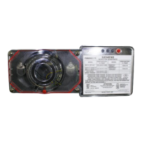
Detector LED The FDBZ492-PR contains an LED indicator (located on the
smoke detector) capable of flashing either one of three distinct
colors: green, yellow, or red. During each flash interval, the
microprocessor based detector checks the following:
• for smoke in its sensing chamber
• that its critical smoke sensing electronics are operating.
Based on the results of these checks, the LED indicator flashes
as follows:
rotceteD
hsalF
roloCnoitidnoC
hsalF
lavretnI
)sdnoceS(
11-EP
4588
C11-EP
neerG.noitarepoyrosivrepuslamroN7
121POnee
rG.noitarepoyrosivrepuslamroN01
11-EP
4588
C11-EP
wolleY
siro)riaperrogninaelc(ecivresseriuqerrotceteD
.snoit
acificepslatnemnorivnestidnoyebgnitarepo
03-7
121POwolleY.tnemecalpersdeendnaelbuortnisirotceteD5
11-EP
4588
C11-EP
121PO
deRmralA½2
11-EP
4588
C11-EP
sehsalFoN.riaperseriuqerroderewoptonsirotceteD__
121POsehsalFoNroderewop
tonsirotceteDdedeensitnemecalper.__
MOUNTING THE AIR DUCT HOUSING
Location on Duct System
This guideline contains general information on duct smoke
detector installation, but does not preclude the NFPA docu-
ments listed. Siemens Industry, Inc. assumes no responsibility
for improperly installed duct detectors. To determine the correct
installation position for an FDBZ492-PR duct smoke detector, the
following factors must be considered.
1) A uniform non-turbulent (laminar) airflow between 100 ft/
min. to 5,000 ft/min. must be present in the HVAC duct. To
determine duct velocities, examine the engineering
specifications that define the expected velocities or use an
Alnor model 6000AP velocity meter (or equivalent).
2) To minimize the impact of air turbulence and stratification
on performance, a duct smoke detector should be located
as far as possible downstream from any obstruction (i.e.
deflector plates, elbows, dampers, etc.). In all situations,

 Loading...


