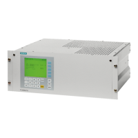
Pin assignment diagram FIDAMAT 5E-E
X3
25
RXD–
24
10
9
TXD–
TXD+
RXD+
2
7
3
1
TXD
GND
V24
Screen
TTY
RXD
Calibrate span (funct. 8)
Limit 2
Measure
Calibrate
Limit 3
Limit 4
Status
signal
Calibrate zero (funct. 5)
Vacant
Analog current –
MR 3
Ready
Not Ready
Measuring range identification
Contact closed = MR active
Status
signal
13
12
13
25
24
23
15
22
21
20
19
17
16
14
Limit 1
Analog current –
MR 4
11
10
9
8
2
7
6
5
4
18
3
1
Connection sideDevice side
Pin
Connection sideDevice side
Pin
Analog current +
MR 2
MR 4
MR 1
X1
Contact open =
limit triggered
X2
12
Limit 3
E2
11
10
9
13
Connection side
Device side
Pin
Valve for hydrogen
E1 closed triggers a single
autocalibration
E2 closed = E1 is activated
Valve for calibration gas 3
13
25
24
23
15
22
21
20
19
18
16
14
No warning
Connection side
Device side
Pin
Warning
17
Valve for calibration gas 4
Valve for calibration gas 2
Valve for zero gas
Valve for calibration gas 1
E1
Signal contact “Calibrate” (closed =
calibration being carried out
Ground
Vacant
Limit 4
Limit 1
Limit 2
Contact closed =
limit triggered
8
2
7
6
5
4
3
1
Contact
open =
valve off
(closed)
14

 Loading...


