Section 6: Minor Replacements and Adjustments, Page 6—19
4. Carefully rotate the panel up and back.
The circuit board cover is connected to the instrument by the two connectors of the
LOW STAIN and POWER lights. Rotate the panel carefully so the connectors are not
pulled loose.
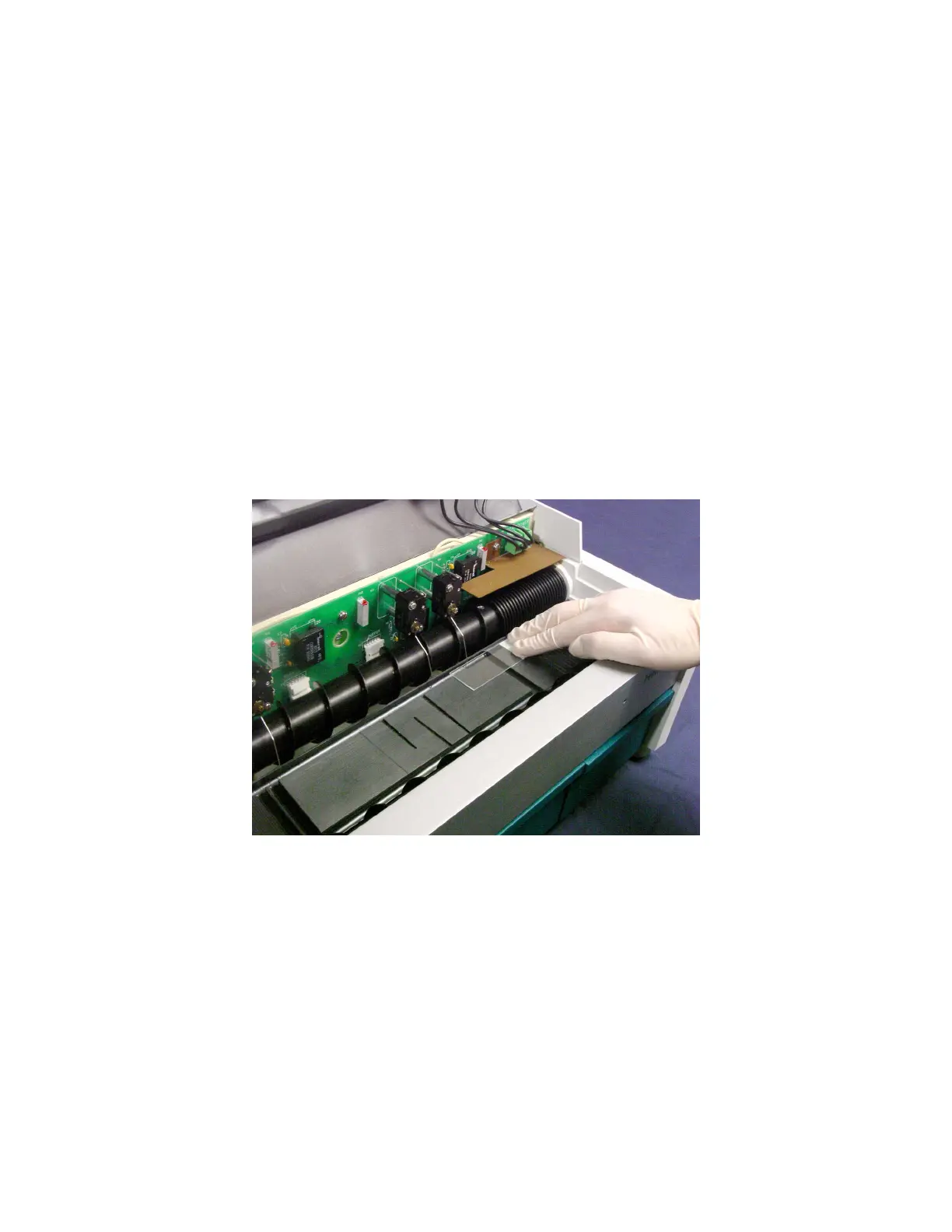
5. Check the location of each of the sensing switch fingers for the following two criteria:
Each finger should point straight down into the center of the back trough of the platen,
without touching the bottom.
If it is not, bend the finger slightly forward or backward as necessary, as directed
below.
The sensing switch should be activated before the finger is lifted over the top surface
of the slide.
6. Lay a slide lengthwise along the back edge of the platen and slowly push the slide
from right to left past the sensing switch finger, listening for a slight click as the
sensing switch is activated.
If the click is not occurring before the finger has been lifted onto the top of the slide,
bend the finger slightly to the right, as directed below.
Figure 6-18. Checking for Adjustment of Sensing Switch Fingers