GAMMA instabus
Release: February 2012
KNX EIB TP-UART 2-IC
Technical Manual pages 42 Siemens AG
Infrastructure and Cities Sector,
Building Technologies
page 8 © Siemens AG 2012 Control Products and Systems
Subject to change without further notice. P. O. Box 10 09 53,
D-93009 Regensburg
DI_PD ... digital input with pulldown
DIO_PU ... digital I/O with pullup
DO ... digital output
DO_PU ... digital output with pullup
NC ... Not connected. Recommend to be tied to VB in the application.
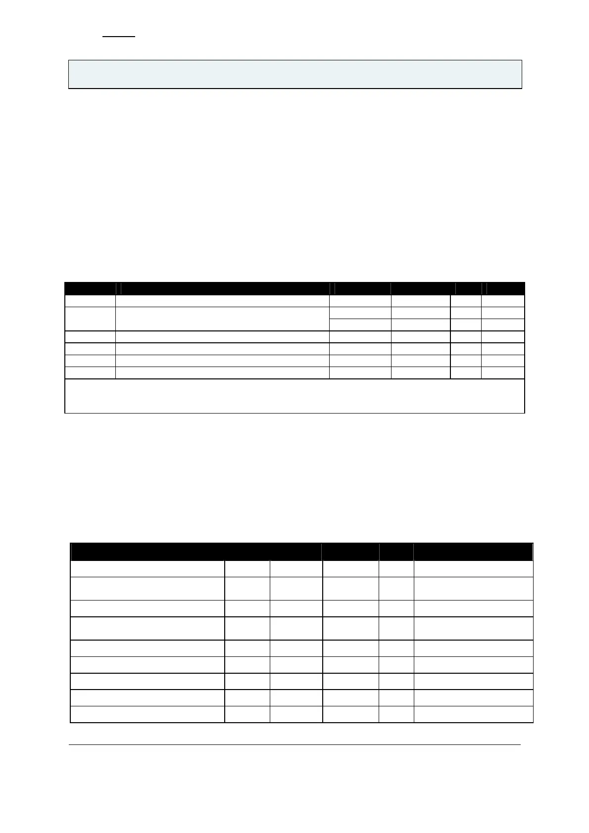
2.2 OPERATING CONDITIONS
2.2.1 General operating conditions
All specification parameters, unless otherwise stated, are valid within the General operating conditions.
Unless otherwise stated all voltages are referenced to the VB- pin.
Symbol Parameter Min Max Unit Note
VB+ positive line voltage 11 45 V 1)
5.0 - 5% 5.0 + 5% V 2) V
CC
positive supply voltage for external supply
(digital test modes with SHB = 0)
3.3 - 5% 3.3 + 5% V 2)
V
IF
positive external supply voltage 3.0 5.5 V
T
amb
ambient temperature -25 85 ºC
T
jnc1
Junction temperature 125 ºC
f
clk
clock frequency (external quartz) 4.9152 MHz
3)
1) DC voltage of bus is 20V to 30V, with signal and compensation pulse 11 V ... 45 V
2) set by SVCC
3) 4.915MHz external clock running
Table 3 General operating conditions
2.2.2 ABSOLUTE MAXIMUM RATINGS (NON OPERATING)
Stresses beyond those listed under “Absolute Maximum Ratings“ may cause permanent damage to
the device. These are stress ratings only. Functional operation of the device at these or any other
conditions beyond those indicated under “Operating Conditions” is not implied. Exposure to absolute
maximum rating conditions for extended periods may affect device reliability. Unless otherwise stated
all voltages are referenced to the VB- pin.
Parameter Symbol Min Max Unit Note
positive line voltage VB+ -0.3 50 V 1)
positive supply voltage (internal or
external supply)
V
CC
-0.3 7 V 2)
positive external supply voltage V
IF
-0.3 7 V 2)
intermediate voltage (generated
by on-chip regulator)
V
VSP
-0.3 50 V 2)
voltage on pin TxO V
TxO
-0.3 50 V 1)
voltage on pin RxIN V
RxIN
-0.3 50 V 1), 4)
voltage on pin BYP V
BYP
-0.3 50 V 1)
voltage on pin STxO V
STxO
-0.3 50 V 1)
voltage on pin V20 V
20
-0.3 25 V 2)