GAMMA instabus
Release: February 2012
KNX EIB TP-UART 2-IC
Siemens AG pages 42 Technical Manual
Infrastructure and Cities Sector,
Building Technologies
Control Products and Systems © Siemens AG 2012 page 9
P. O. Box 10 09 53, Subject to change without further notice.
D-93009 Regensburg
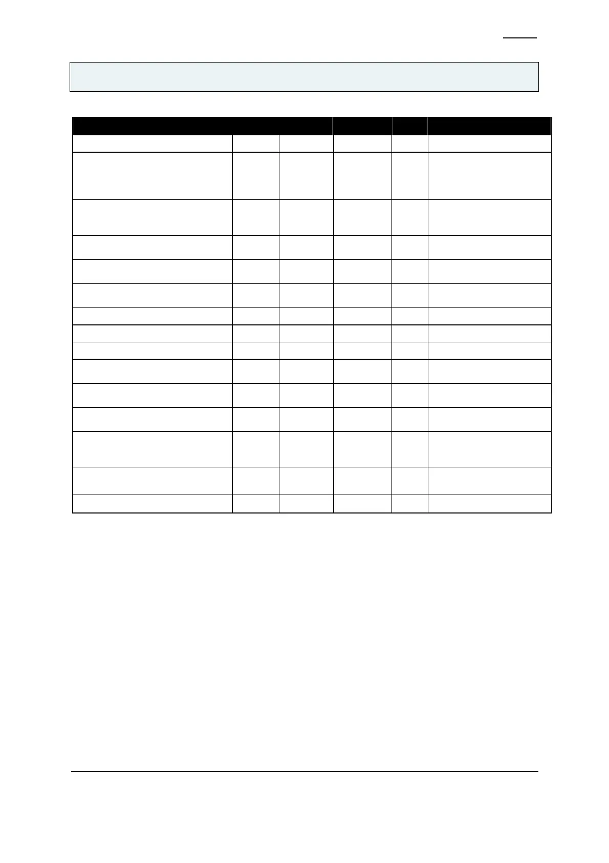
Parameter Symbol Min Max Unit Note
voltage on pin IND V
IND
-0.3 50 V
voltage on low voltage pins
MODE0, MODE1, MODE2,
MODE3, TSTIN_BDS,
TESTMODE, DIV, SVCC, CTM
V
LV1
-0.3 V
DP
+0.5 V 9)
voltage on low voltage pins TxD,
RESn, TSTOUT_TW, X1, X2,
RxD, SAVE
V
LV2
-0.3 V
IF
+0.5 V 5)
Internal supply voltage to digital
part
V
VDP
-0.3 5 V
voltage used for internal DC/DC-
converter
V
VDDH
-0.3 50 V
voltage used for internal DC/DC-
converter
V
VSSH
-0.3 50 V
Ambient temperature T
amb
-25 85
ο
C
Junction temperature T
j
145
ο
C
storage temperature T
S
-65 150
ο
C
ESD stress voltage that will not
cause damage to the device
V
ESD
± 1200 V 3)
static current for latchup
initialization
I
LATCHUP
± 50 mA
thermal resistance of QFN
package to ambient
R
tha
28 K/W 6)
thermal resistance of QFN
package to package surface
measured on exposed paddle
R
ths
5 K/W 6)
Total power dissipation at T
amb
=
85
ο
C (all supplies and outputs)
P
t
1.4 W TW not active 7)
Humidity noncondensing H
NC
5 93 % 8)
Table 4 Absolute maximum ratings
Notes:
(1) during surge impulse: 20 V for 2 sec and +65 V for 150 sec
(2) In particular allowed voltage relations (no damage under following voltage relations):
(a) V
VSP
≥ VB+; e.g. VB+ = 0 V due to a short circuit
(b) V
V20
≥ V
VSP;
e.g. V
VSP
= 0 V due to a short circuit or VB+ = 0 V
(c) V
VCC
≥ V
VSP;
e.g. V
VSP
= 0 V due to a short circuit or VB+ = 0 V
(d) V
IF
≥ V
VCC
; e.g. when an external supply for V
IF
is used and VB+ = 0 V
(e) V
CC
and V
VSP
normal / VB+ and V
IF
can be 0 V
(f) V
VSP
normal / V
CC
, VB+ and V
IF
can be 0 V
(g) V
IF
normal / V
CC
, VB+ and V
VSP
can be 0 V
(h) V
DP
≥ V
VSP
; e.g during normal startup sequence.
(3) human body model: 100 pF, 1.5 kΩ, Mil. Std. 883, method 3015.7
(4) dynamic via C
REC
= 47 nF in case of switchingon/off the bus voltage, complies with V
CREC
at normal
operation, may be down to 20 V.
(5) max. 7 V
(6) Measurement conditions in accordance with EIA/JEDEC STANDARD 512. Value is an estimate only.