6/8 CC1N7781E June 01, 1999 Landis & Staefa Division
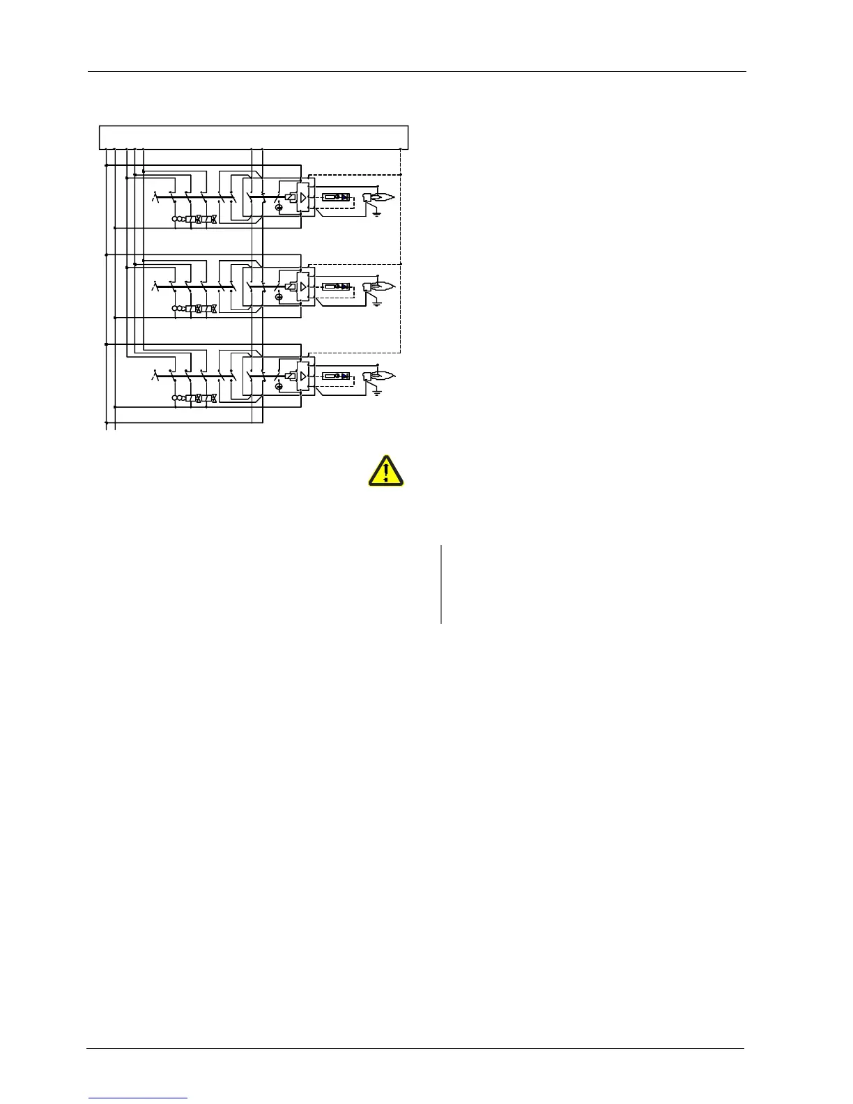
Detailed connection diagram (e.g. for gas burners)
75621
P(R) N(Mp)
BS
I0
Z
GV1 GV2
10
9
FR
L1
2
LFE10
7 5
+
QRA...
FE
BS
Z
GV1 GV2
I0 L1
2
LFE10
7 5
163 4
8
163 4
10
9
8
FR
BS
I
0
Z
GV1 GV2
16
3 4
10
9
8
FR
L1
2
LFE10
7 5
13
LEC1
14
+
QRA...
FE
+
QRA...
FE
15
7781a03/1198
Mode of operation of flame safeguards with multi-flame
supervision
Like with dual-supervision, the control contacts of the flame relays of
all flame safeguards must be connected in series.
A burner causes all other burners to go to lockout if
– the flame is not established during the safety time, or
– the flame is lost during operation
Correctly operating burners can be restarted only - after the burner
control has been reset - when the faulty burner has been shut down.
In that case, the operating switch must not only bridge the control
contacts of the respective flame safeguard, thus closing the control
chain again, but must also break the phase wire connection to the
ignition transformer and the fuel valves.
Likewise, after rectification of the fault, the burner can only be
restarted in connection with the other burners, that is, only after all
burners have previously been shut down.
Terminal 10 must be connected to earth also when using the UV
detector QRA...
BS Operating switch OFF / ON
→ Per burner
L1 Built-in signal lamp
→ Indication of flame
FE Detector electrode for flame rectification QRA... UV detector
FR Flame relay Z Ignition transformer
GV1/...2 Gas valves 1
st
and 2
nd
stage
Legend

 Loading...