Landis & Staefa Division CC1N7781E June 01, 1999 7/8
Basic circuit diagrams
P(R)
H
6157
15 LEC1
10
13
3
hr3
2
N(Mp)
14 LEC1
HR3
8
9
4
FR
L1
+
RAR...
7781a04/1198
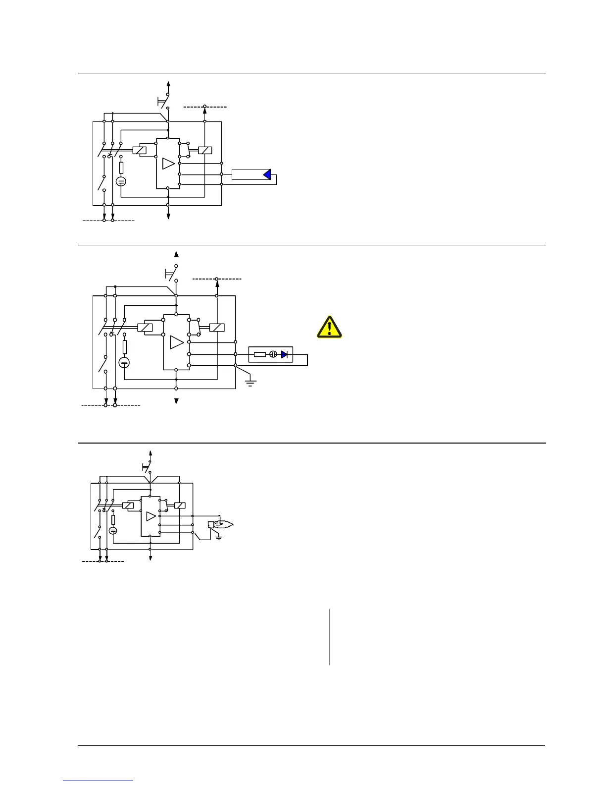
LAE10
With selenium photocell detector RAR...
P(R)
H
6157
15 LEC1
10
13
3
hr3
2
4
N(Mp)
14 LEC1
HR3
8
9
FR
L1
QRA...
+
7781a05/0199
LFE10
With UV detector QRA...
Terminal 10 must be connected to earth!
P(R)
H
10
13
3
7
hr3
24
N(Mp)
14 LEC1
615
HR3
9
FR
L1
8
7781a06/0199
FE
LFE10
With flame rectification probe
FE Detector electrode for flame rectification L1 Built-in signal lamp
FR Flame relay → Indication of flame
H Main isolator QRA... UV detector
HR3 Auxiliary relay for UV detector or flame simulation
test
RAR... Selenium photocell detector
Legend

 Loading...